
Electronic Voltmeter Ammeter Circuit Using Single IC 741

The electronic multimeter circuit is composed of several key components that work together to provide accurate measurements across multiple ranges. The operational amplifier (op-amp) 741 serves as the central element for voltage comparison, utilizing its high gain to amplify the minute differences between the reference voltage (set by VR1) and the input voltage. The arrangement of resistors R1 to R5 is critical for defining the measurement ranges. Each resistor is selected based on its tolerance to ensure the accuracy of readings, particularly in the current measurement modes where the resistance values directly influence the voltage drop and, consequently, the output of the op-amp.
In the voltage measurement mode, the multimeter's design allows for the detection of both DC and AC voltages. The inclusion of diode D1 and capacitor C1 is essential for handling AC signals, where the capacitor acts as a peak detector, charging when the input voltage exceeds a certain threshold and discharging in a controlled manner to maintain the LED indicator's illumination.
For current measurements, the circuit employs a shunt resistor configuration, where the current flowing through R4 and R5 is converted into a voltage drop that can be compared against the reference voltage. This method ensures that the multimeter can accurately measure both low and high current levels while providing a clear visual indication of the measurement status through LED D2.
The calibration process is straightforward, allowing users to set the multimeter against a known standard. This feature is particularly advantageous for hobbyists who may not have access to high-precision measuring instruments. The flexibility in resistor selection and the ability to modify the circuit for extended ranges make this electronic multimeter a versatile tool for various applications, from basic electronics projects to more advanced measurements.Simple Electronic Multimeter High cost deters many hobbyists from buying a conventional multimeter. Since it is difficult to obtain cheap 50 uAor 100uA meters which are essential for a highly sensitive multimeter, an electronic alternative device is suggested to serve the purpose. The circuit shown here gives economic and safe ranges covered to th ree values : (i) 0-15V, (ii) 0- l5mA, and (iii) 0-150mA. The ranges can be extended with suitable modifications. The 741 operational amplifier acts as a null detector. its output is equal to the voltage at point A minus the voltage at, point B, multiplied by the device`s very high voltage gain. lf VA is slightly greater than VB, the output is limited by the supply voltage to about 7 volts. lf VA is slightly less than VB, the output is about 2 volts. At the point at which the output changes from low to high or vice-versa, VA is equal to VB to within a very small margin of error.
With the switch set to the position shown in circuit diagram (15V range) the potential difference between points A and C is The forward voltage drop of the diode D3 is about 0. 6V and largely independent of battery condition. About 0. 5V appears across the variable resistance VRl and a known fraction of this indicated by a scale on the potentiometer appears between points A and C, i.
e. it compares the known reference voltage with a known fraction of the input voltage. On the two current ranges, the reference potential difference is compared with the voltages developed across R4 plus R5 on the l5mA range and R5 only in 150mA range. T `D2, a light emitting diode, with its current limiting series resistor R9 indicates whether the output of the operational amplifier is high or low.
The diode D1 and the condenser Cl provide the facility of measuring alternating voltages and currents. lf the voltage at A momentarily exceeds the voltage at B, then Cl will charge up via Dl maintaining D2 »alight until the peak of the next cycle.
Without Cl there is no sharp point at which D2 extinguishes for AC measurement. ln use it must be remembered that the indicated readings are all peak values and will thus need to be divided by square-root of 2 to give RMS value for a sinusoidal input. The meter is calibrated directly VRl is scaled 0-15 on the _ 15V range by comparison with a standard meter.
This calibration will hold quite closely for current ranges ”the agreement depending on the tolerances of Rl to R5. Ten per cent tolerance resistors have been found to be quite successful for these but, if desired, 5 or even 2 per cent resistors provide a worthwhile increase in the accuracy of the current ranges.
ln use, the meter is switched to the appropriate range and V connected as for a conventional multimeter. The potentiometer VR] is rotated until D2 is at the point of changing from off to on and then the reading is directly indicated.
on the potentiometer scale. The diodes may be any silicon diode. For use of the multimeter in 0- l 50V range, the values of the resistors Rl to R5 may be changed proportionately so that the value of the ratio is l/300. Then with these values, the multimeter will operate on 0- l 5OV range in the first position (as shown in the existing diagram).
The accuracy no doubt will be somewhat ham- pered. VRl has to be calibrated accordingly. 🔗 External reference
Related Circuits
The following circuit illustrates a Bass and Treble Controller Circuit. This circuit is constructed based on the classic Baxandall tone control circuitry. The Bass and Treble Controller Circuit is designed to adjust the low and high-frequency response of audio signals,...
Here is a simple schematic of a TV transmitter circuit, or video transmitter circuit, capable of broadcasting in the VHF range from 60 to 200 MHz. The input video source can be any CCD camera or VCR. The output...
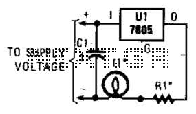
A 7805 can be configured as a constant-current regulator to function as an inrush current limiter. Resistor R1 will maintain a voltage of 5 V across it at all times, resulting in a total current through R1 of 5...
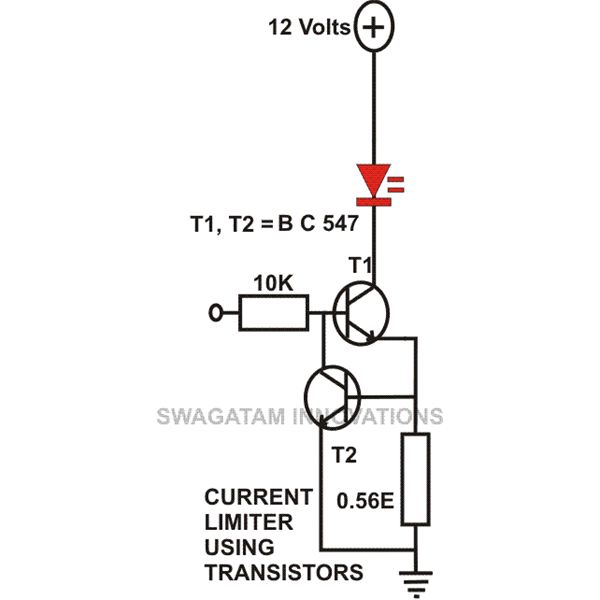
This article compiles small transistor circuits and configurations suitable for beginners, including current amplifiers, limiters, oscillators, and latches. A simple current amplifier circuit can be constructed using just a couple of NPN transistors. Additionally, two transistors and resistors can...
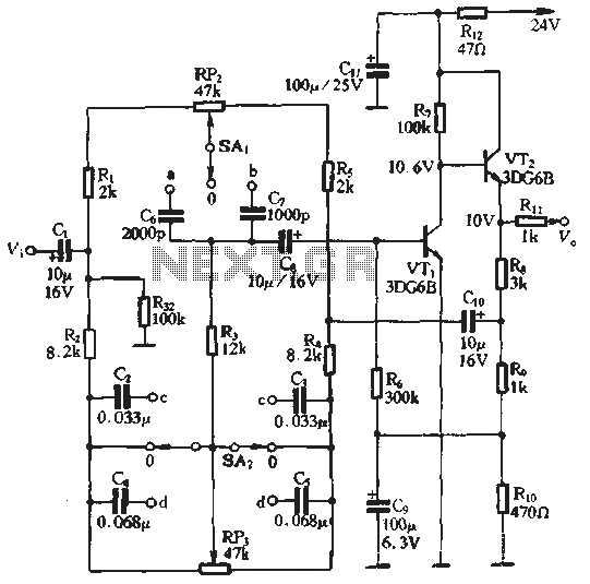
An attenuation switch is utilized to modify the pitch of a feedback control circuit's transition frequency, specifically for two treble controls. RP3 is designated for bass control, while SA1 and SA2 are employed to adjust the high bass control...
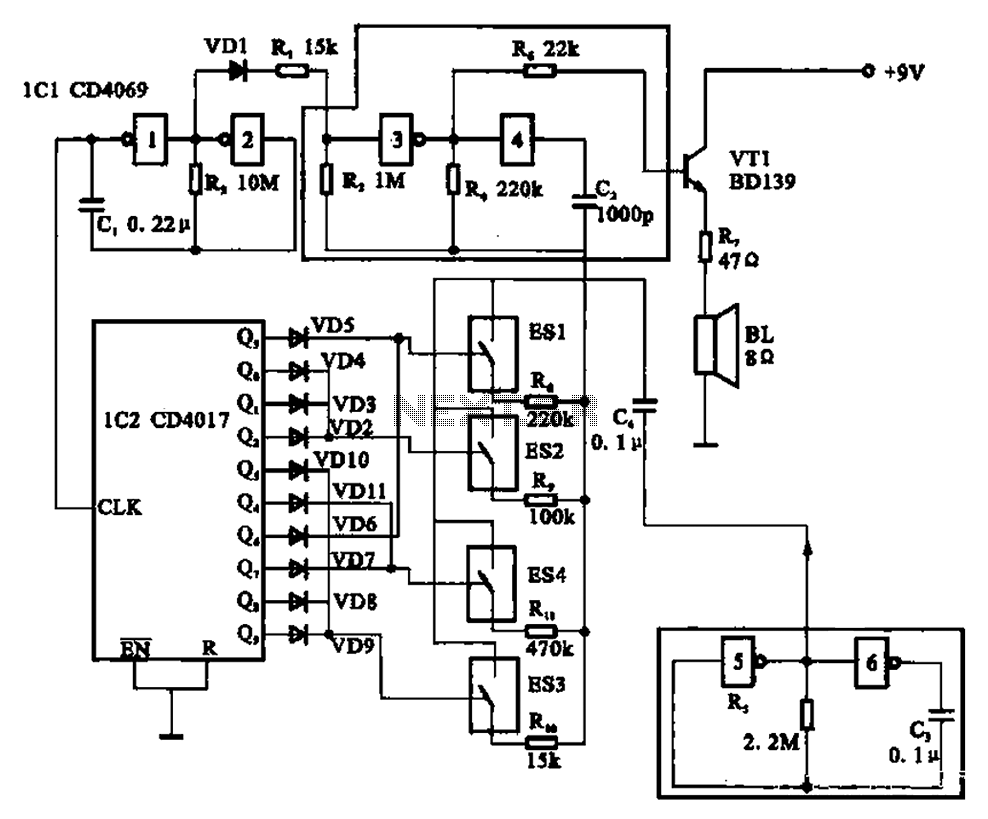
The circuit illustrated is an analog signal generator designed to produce a chirping sound, simulating birds singing. It employs six CD4069 inverters to create three oscillators, with two of them functioning as ultra-low frequency oscillators. The oscillation frequency is...