
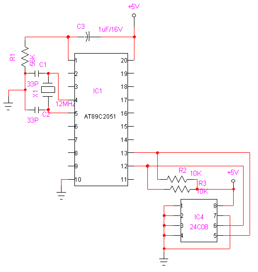
serial eeprom interfacing at24c08 with at89c2051
The assembly code begins by defining the SDA and SCL pins, followed by the write and read commands for the EEPROM. The routines provided demonstrate how to store a byte in a specific address location within the EEPROM and how to retrieve a byte from a designated address. The code includes detailed comments explaining each step of the process, including the generation of start and stop conditions, which are essential for proper communication with the EEPROM.
The write operation involves loading the write command into the accumulator, sending the address location, and then transmitting the data byte. After the data is sent, a stop condition is issued to terminate the communication. Conversely, the read operation begins with loading the read command, sending the address, and then retrieving the data byte, which is stored in a register for further processing.
The routines also include mechanisms for handling acknowledgments (ACK) from the EEPROM, ensuring that the write operations are completed successfully before proceeding. The code is structured to allow for efficient data transfer and management, adhering to the protocols established for serial EEPROM communication.
The serial EEPROM communication relies on two main protocols: the 2-wire I2C (Inter-Integrated Circuit) and the 3-wire SPI (Serial Peripheral Interface). The choice of protocol depends on the specific application requirements, such as speed, complexity, and the number of devices on the bus.
In summary, the assembly code effectively demonstrates the fundamental operations required to interface with serial EEPROMs, providing a clear and structured approach to data management in embedded systems. This implementation is crucial for applications requiring non-volatile memory storage, enabling the retention of data even when power is removed. The detailed comments and structured routines make it an invaluable resource for engineers and developers working with EEPROM technology.Microchip has addressed this need with a full line of serial EEPROMs, in a variety of memory configurations, using the industry-standard 2- or 3-wire communication protocols. SDA1 EQU P1. 1 ;SDA=PIN5 SCL1 EQU P1. 0 ;SCL=PIN6 WTCMD EQU 10100000B ;WRITE DATA COMMAND RDCMD EQU 10100001B ;READ DATA COMMAND ; STORE A BYTE IN EEPROM
(Data 8F in address location 2AH) ; MOV A, #WTCMD ;LOAD WRITE COMMAND CALL OUTS ;SEND IT MOV A, #2AH ;GET BYTE ADDRESS CALL OUT ;SEND IT MOV A, #8FH ;GET DATA CALL OUT ;SEND IT CALL STOP ;SEND STOP CONDITION ; READ A BYTE FROM EEPROM FROM ADDRESS LOCATION 4DH ; MOV A, #WTCMD ;LOAD WRITE COMMAND TO SEND ADDRESS CALL OUTS ;SEND IT MOV A, #4DH ;GET LOW BYTE ADDRESS CALL OUT ;SEND IT CALL CREAD ;GET DATA BYTE MOV A, R1 CALL MDELAY RET ;* ; EEPROM ROUTINES ;* ;* ; THIS ROUTINE SENDS OUT CONTENTS OF THE ACCUMULATOR ; to the EEPROM and includes START condition. Refer to the data sheets ; for discussion of START and STOP conditions. ;* OUTS: MOV R2, #8 ;LOOP COUNT - EQUAL TO BIT COUNT SETB SDA1 ;INSURE DATA IS HI SETB SCL1 ;INSURE CLOCK IS HI NOP ;NOTE 1 NOP NOP CLR SDA1 ;START CONDITION - DATA = 0 NOP ;NOTE 1 NOP NOP CLR SCL1 ;CLOCK = 0 OTSLP: RLC A ;SHIFT BIT JNC BITLS SETB SDA1 ;DATA = 1 JMP OTSL1 ;CONTINUE BITLS: CLR SDA1 ;DATA = 0 OTSL1: SETB SCL1 ;CLOCK HI NOP ;NOTE 1 NOP NOP CLR SCL1 ;CLOCK LOW DJNZ R2, OTSLP ;DECREMENT COUNTER SETB SDA1 ;TURN PIN INTO INPUT NOP ;NOTE 1 SETB SCL1 ;CLOCK ACK NOP ;NOTE 1 NOP NOP CLR SCL1 RET ;* ; THIS ROUTINE SENDS OUT CONTENTS OF ACCUMLATOR TO EEPROM ; without sending a START condition.
;* OUT: MOV R2, #8 ;LOOP COUNT - EQUAL TO BIT COUNT OTLP: RLC A ;SHIFT BIT JNC BITL SETB SDA1 ;DATA = 1 JMP OTL1 ;CONTINUE BITL: CLR SDA1 ;DATA = 0 OTL1: SETB SCL1 ;CLOCK HI NOP ;NOTE 1 NOP NOP CLR SCL1 ;CLOCK LOW DJNZ R2, OTLP ;DECREMENT COUNTER SETB SDA1 ;TURN PIN INTO INPUT NOP ;NOTE 1 SETB SCL1 ;CLOCK ACK NOP ;NOTE 1 NOP NOP CLR SCL1 RET STOP: CLR SDA1 ;STOP CONDITION SET DATA LOW NOP ;NOTE 1 NOP NOP SETB SCL1 ;SET CLOCK HI NOP ;NOTE 1 NOP NOP SETB SDA1 ;SET DATA HIGH RET ;* ; THIS ROUTINE READS A BYTE OF DATA FROM EEPROM ; From EEPROM current address pointer. ; Returns the data byte in R1 ;* CREAD: MOV A, #RDCMD ;LOAD READ COMMAND CALL OUTS ;SEND IT CALL IN ;READ DATA MOV R1, A ;STORE DATA CALL STOP ;SEND STOP CONDITION RET ;* ; THIS ROUTINE READS IN A BYTE FROM THE EEPROM ; and stores it in the accumulator ;* IN: MOV R2, #8 ;LOOP COUNT SETB SDA1 ;SET DATA BIT HIGH FOR INPUT INLP: CLR SCL1 ;CLOCK LOW NOP ;NOTE 1 NOP NOP NOP SETB SCL1 ;CLOCK HIGH CLR C ;CLEAR CARRY JNB SDA1, INL1 ;JUMP IF DATA = 0 CPL C ;SET CARRY IF DATA = 1 INL1: RLC A ;ROTATE DATA INTO ACCUMULATOR DJNZ R2, INLP ;DECREMENT COUNTER CLR SCL1 ;CLOCK LOW RET ;* ; This routine test for WRITE DONE condition ; by testing for an ACK.
; This routine can be run as soon as a STOP condition ; has been generated after the last data byte has been sent ; to the EEPROM. The routine loops until an ACK is received from ; the EEPROM. No ACK will be received until the EEPROM is done with ; the write operation. ;* ACKTST: MOV A, #WTCMD ;LOAD WRITE COMMAND TO SEND ADDRESS MOV R2, #8 ;LOOP COUNT - EQUAL TO BIT COUNT CLR SDA1 ;START CONDITION - DATA = 0 NOP ;NOTE 1 NOP NOP CLR SCL1 ;CLOCK = 0 AKTLP: RLC A ;SHIFT BIT JNC AKTLS SETB SDA1 ;DATA = 1 JMP AKTL1 ;CONTINUE AKTLS: CLR SDA1 ;DATA = 0 AKTL1: SETB SCL1 ;CLOCK HI NOP ;NOTE 1 NOP NOP CLR SCL1 ;CLOCK LOW DJNZ R2, AKTLP ;DECREMENT COUNTER SETB SDA1 ;TURN PIN INTO INPUT NOP ;NOTE 1 SETB SCL1 ;CLOCK ACK NOP ;NOTE 1 NOP NOP JNB
🔗 External reference
Related Circuits
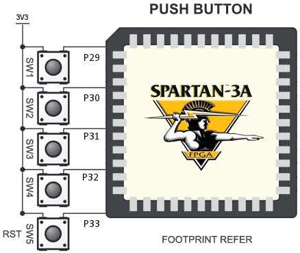
The Spartan-3an board features eight slide switches, as illustrated in the accompanying figure. The push button inputs are typically in a low state and transition to a high state only when the button is pressed. These push buttons are...
This resource provides a variety of PIC Microcontroller tutorials that cater to both beginners and advanced users. These tutorials enable individuals to gain expertise in microcontroller programming and circuit design without the need for costly embedded system courses. The tutorials...
This interface design has a long history. It is the first microcontroller design initiated in early 1998, which has evolved over the years. Initially, the schematic diagram for the first prototype was drafted in 1998, and it later became...
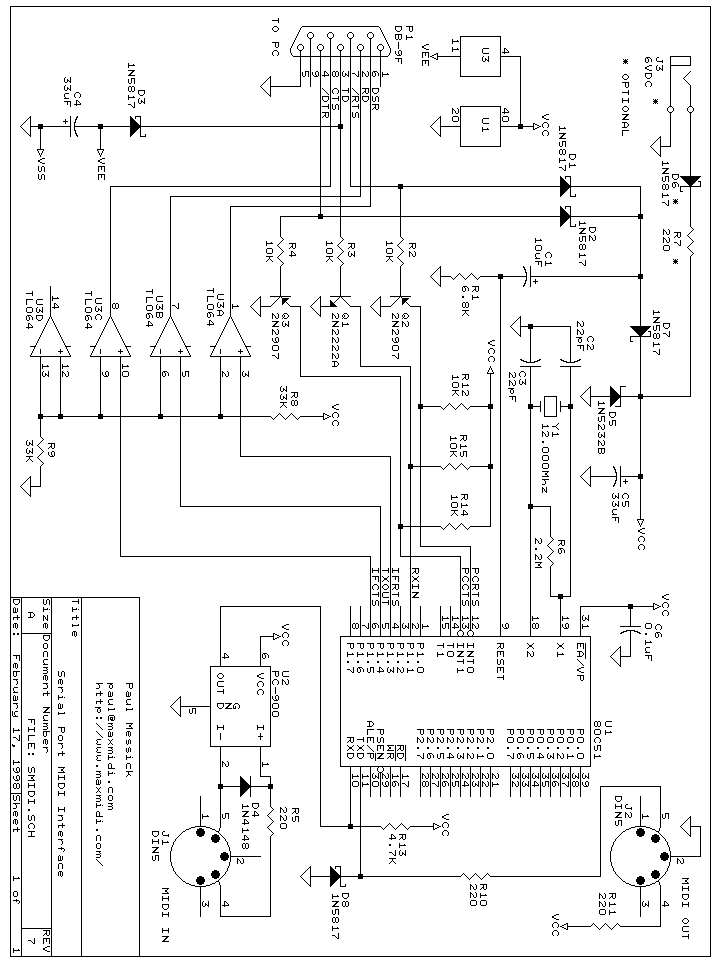
This page describes how to build this full-bandwidth single-port (one input and one output) MIDI interface. The interface is buffered (that is, if the PC gets behind you won’t lose data) and it works in Windows 3.1 and Windows...
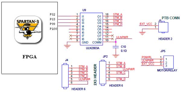
The Spartan-3 Primer board features external stepper motor interfacing, as illustrated in the accompanying figure. The stepper motor is driven by a ULN2803A, which is a high-voltage, high-current Darlington transistor array. The ULN2803 is utilized as a driver for...
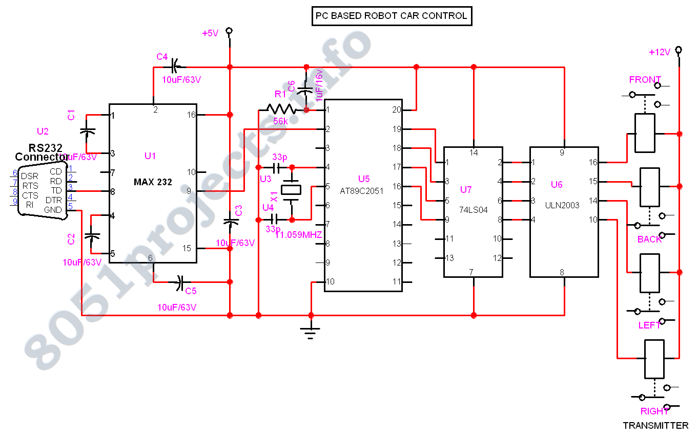
The advent of new high-speed technology and the growing computer capacity provided realistic opportunity for new robot controls and realization of new methods of control theory. This technical improvement together with the need for high performance robots created faster,...