
Serial programmer circuit for AT89Sx MCUs

The microcontroller within the programmer can operate even when the computer is turned off or disconnected. The transistors used in the design can be substituted with nearly any universal low-frequency transistors that have the same pin configuration. Incorrect resistor values may lead to malfunction, so it is advisable to prototype the circuit on a solderless breadboard before committing to a printed circuit board (PCB) design and soldering. The RS-232 connector on the board is of the female type. A reset button is included to reset the microcontroller connected to the programmer. It is important to note that hardware connected to the microcontroller ports may cause the programmer to malfunction. The power supply requirement is between 8 to 30 volts, with the programmer functioning at 5 volts. LED1 indicates when the power is on, while LED2 signifies PC activity or an uninitialized programmer. The ISP programming cable allows the programmer to program a microcontroller, for example, on a breadboard or a PCB. However, it should be noted that communication can only occur with one microcontroller at a time, necessitating the removal of the microcontroller placed in the socket on the programmer board before programming another.
The RS-232 ISP programmer circuit is a straightforward design that facilitates the programming of AT89Sx devices through a serial interface. The system architecture includes a microcontroller that manages the programming process and interfaces with the computer through the RS-232 protocol. The use of the PL2303 chip allows for seamless USB to serial communication, which is essential for modern computer systems lacking traditional serial ports.
The power supply circuit should include voltage regulation to ensure that the microcontroller operates reliably at 5V, even if the input voltage varies between 8V and 30V. The inclusion of a reset button adds a layer of convenience, allowing users to easily reset the microcontroller without needing to power down the entire system.
The programmer's design should incorporate indicators such as LED1 and LED2 to provide visual feedback on the operational status. LED1 serves as a power indicator, while LED2 can be used for debugging purposes by indicating when the programmer is actively communicating with the computer or when it is uninitialized.
In terms of hardware considerations, careful selection of resistors and transistors is crucial to avoid potential malfunctions. The circuit layout should be optimized to minimize noise and interference, particularly in the signal lines connecting to the microcontroller ports. To facilitate ease of use, the RS-232 connector should be clearly labeled, and the ISP programming cable should be designed to connect securely to both the programmer and the target microcontroller.
For prototyping, a solderless breadboard allows for flexibility and experimentation with component values and arrangements before finalizing the design on a PCB. This approach helps identify any potential issues in the circuit design, particularly with respect to the interactions between the programmer and the microcontroller being programmed.Simple RS-232 ISP programmer for AT89Sx devices. This device is intended for education purposes and for hobbyists. It has been tested with AT89S2051 and AT89S8253 along with USB to serial port converter cable (with PL2303 chip). MCU in programmer can work while computer is turned off or disconnected. Transistors can be replaced with almost any universal low frequency transistors with the same pinout. Bad resistor values may cause malfunction. It might be a good idea to try it in solderless breadboard before making PCB and soldering. RS-232 connector on the board is female. Reset button resets MCU connected to the programmer. Hardware connected to the MCU ports may cause programmer malfunction. Power supply: 8 → 30 V (Programmer work with 5V) LED1: Indicates power on LED2: Indicates PC activity or uninitilized programmer ISP programming cable: Trough this interface programmer should be able to program MCU for instance in breadboard or some PCB.
But remember it can comunicate with only one MCU at the time. So MCU placed in the socket on the programmer board must be removed firts. 🔗 External reference
Related Circuits
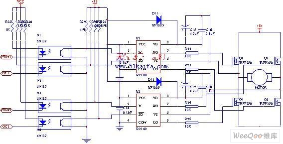
The drive circuit for the electromotor comprises a FET bridge circuit, a FET base drive circuit, a current sensor for the motor drive circuit, and a relay. The FET bridge circuit primarily consists of four high-power MOSFETs, which must...

The circuit includes the TC620 temperature control circuit, the temperature indicator circuit, a thyristor-controlled heating circuit, a vocal music buck rectifier circuit, and the AC circuit. The TC620 temperature control circuit is designed to regulate temperature by monitoring the temperature...

The circuit illustrated in Figure 3-130 differs from the circuit in Figure 3-129 in that when the stop button SB3 is pressed, the electric motor initiates braking. Furthermore, during both the startup and braking phases, the motor power lines...

An advantage of a photogate over a sound trigger is that the former activates based on the exact position of the object that interrupts the beam. For instance, the shape of a snapped elastic cord can be captured as...

This is a NiMH battery charger using the IC LTC4060, which is powerful, effective, and efficient. The LTC4060 IC specializes in NiMH battery charging, ensuring safe operation with features such as battery temperature protection during charging. It includes a...

The 1C foot VIII developed a training device, utilizing the trigger terminal CI for a positive input pulse. It concludes by providing a quotient output level. The system involves a commercial electric circuit featuring a buck converter, which limits...