
TC620 temperature sensor circuit diagram of automatic heating temperature control
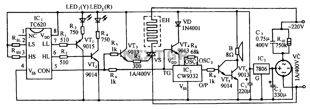
The TC620 temperature control circuit is designed to regulate temperature by monitoring the temperature sensor input and providing a control output. This output can be used to drive a thyristor in the heating circuit, which modulates the power delivered to a heating element based on the desired temperature setpoint. The temperature indicator circuit typically consists of a display that shows the current temperature, allowing for easy monitoring of the system's performance.
The thyristor-controlled heating circuit utilizes a thyristor to switch the heating element on and off rapidly, enabling precise temperature control. The firing angle of the thyristor can be adjusted based on the feedback from the temperature sensor, allowing for smooth control of the heating process.
The vocal music buck rectifier circuit is designed to convert AC voltage to a lower DC voltage, suitable for powering audio applications. It typically includes a transformer to step down the voltage, followed by a rectification stage using diodes to convert the AC signal to DC. The output is then filtered to provide a stable DC voltage for audio equipment.
The AC circuit is essential in providing the necessary power supply for the entire system. It connects to the mains and ensures that all components receive adequate voltage and current for operation. The integration of these circuits allows for a comprehensive system capable of temperature regulation and audio processing, making it suitable for various applications where precise control and monitoring are required. Circuit is shown. It includes the TC620 temperature control circuit, the temperature indicator circuit, thyristor controlled heating circuit, vocal music buck rectifier circuit and the AC circuit.
Related Circuits
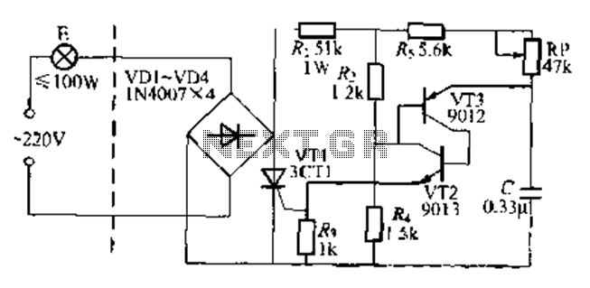
The circuit is a one-way ordinary transistor-triggered dimmer light circuit. It uses a complementary amplifier configuration with transistors VT2 and VT3 to form the thyristor trigger circuit for VT1. The circuit operates with a 220V alternating current through the...
This is the unedited version of the article "Improved Anode-Circuit Parasitic-Suppression For Modern Amplifier-Tubes," which was published on page 36 of the October 1988 issue of QST. A subsequent discussion on this topic appeared in the September and October...
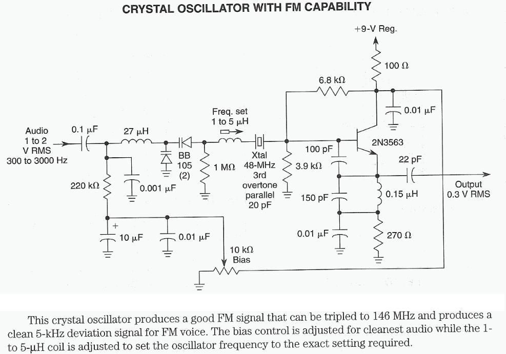
The 7th overtone of 18 MHz (17m) is 144 MHz (2m) directly within the CW region. Icarus is a high-altitude balloon (HAB) project funded by advertising revenue, which has successfully launched numerous balloons that captured impressive photographs. Robert Harrison...
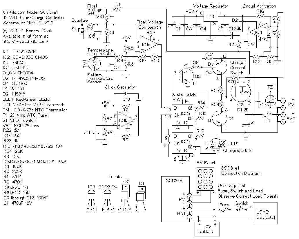
The SCC3 is a solar charge controller. Its function is to regulate the power flowing from a photovoltaic panel into a rechargeable battery. It features easy setup with one potentiometer for the float voltage adjustment, an equalize function for...
The technical parameters of high-speed optocouplers include a rise time (t1) of less than or equal to 300 ns, a circuit transfer ratio (CTR) of 50%, an isolation voltage (VSO) of at least 15,000 V, and an output transistor...
One of the critical components is a PWM speed controller, allowing for fine speed adjustments instead of just an "on" mode that runs at full power. This is important for safety. A basic stamp microcontroller was purchased, which includes...