
Automatic lighting control circuit diagram composed of optocouplers
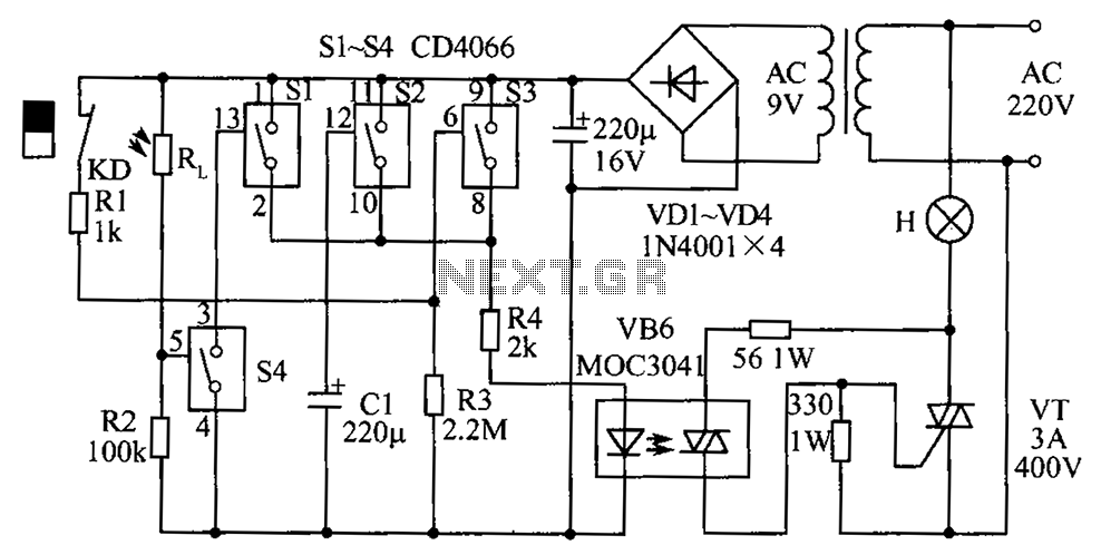
The described circuit operates as an automatic lighting control system that integrates both a delay mechanism and ambient light detection. The primary components include a triac, resistors, capacitors, and a reed switch, all of which work in conjunction to provide a seamless user experience. The triac (VT) serves as a crucial element for controlling the power to the hall lights, enabling them to turn on and off based on the door's status.
The operation begins with the door being closed, which keeps the reed switch (KD) in its normally closed state. When the door is opened at night, the removal of the magnet triggers the closure of the reed switch, allowing the capacitor (C1) to charge rapidly. The charging process is facilitated by the rectification of the 9V power supply through resistor R1, ensuring that the voltage across C1 rises swiftly, thus activating the light-emitting diodes and the thyristor to illuminate the hall lights.
The delay mechanism is an essential feature of this circuit. Once the door is closed again, the reed switch opens, interrupting the charging of C1. The capacitor then begins to discharge through resistor R3, gradually reducing the voltage. This discharge process is critical for determining the time duration that the lights remain on after the door is closed. The circuit is designed to ensure that the voltage across C1 falls below the threshold required to keep switches S1, S2, and S3 in the on state, thus turning off the lights after a set delay.
This automatic lighting control circuit is particularly useful for enhancing convenience and safety in residential settings, providing illumination when needed and conserving energy when it is not. Circuit is shown. Group 4 analog electronic circuit switch (S1 ~ S4): S1, S2, S3 for parallel delay circuit, when the power is turned on by their R4, VB6 drive Triac VT, VT dir ectly control the hall lights H; S4 and external photosensitive resistance RL and the like ambient light detection circuit. When the door is closed, mounted on the door frame normally closed reed KD action by the magnet on the door, its contacts open, S1, S2, S3 in the open state.
Night home owner opened the door, the magnet away from the KD, KD contact closure. After this time 9V power rectifier through R1 to charge C1, C1 two Swiss voltage quickly rises to 9V, the rectified voltage by S1, S2, S3 and R4 within the B6-emitting light-emitting diodes, triggering a two-way thyristor, H is lit., automatic lighting control. After the door closed, the magnet control KD, contact disconnect, 9V power to stop charging C1, entry delay circuit state, C1 began to discharge R3, after a time delay, C1 two Swiss voltage is gradually decreased to S1, S2, 83 open voltage (1.5v) or less, S1, S2, S3 resume off state, resulting in off VB6, VT also cut, H off, lights time-lapse function.
Related Circuits
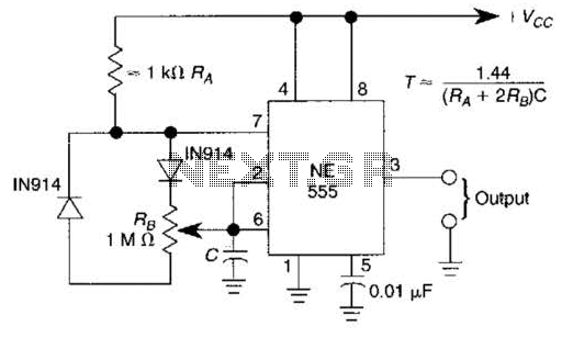
A 1.2-kHz oscillator utilizing a potentiometer and steering diodes allows for a duty cycle adjustment ranging from 1% to 99%. The frequency can be altered by varying the capacitor CI. It is important to note that the diodes may...
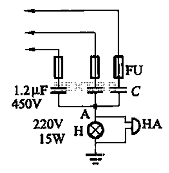
A 3-phase power system poses risks to electrical equipment, particularly asynchronous motors. To detect phase failure, an alarm circuit can be implemented. When the power supply is normal, the voltage at point A is approximately 0V, and no alarm...
A Nidec TA450DC B35502-35 fan has been installed in a large wooden cabinet housing a computer and other electronics, which generates significant heat. The fan is designed to draw air from the room and exhaust it through openings at...

This circuit delivers an initial voltage of 2.5V per cell to rapidly charge a car battery. The charging current decreases as the battery charges. This circuit is designed to provide an efficient charging solution for car batteries by applying an...
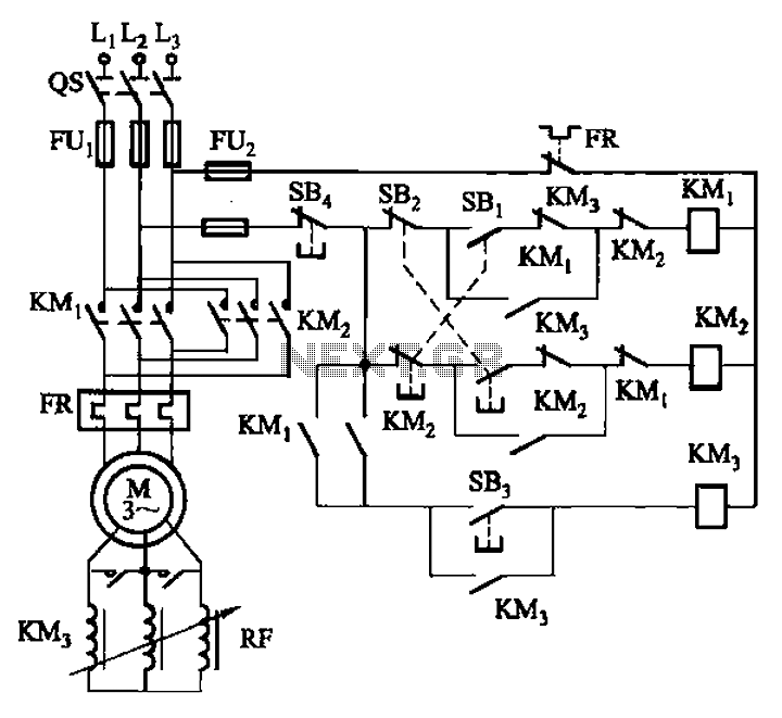
The circuit illustrated in Figure 3-166 employs a button control mechanism. To initiate forward motion, the user presses button SB1, which activates the motor rotor through a frequency-sensitive rheostat (RF). As the motor speed approaches its rated speed, a...
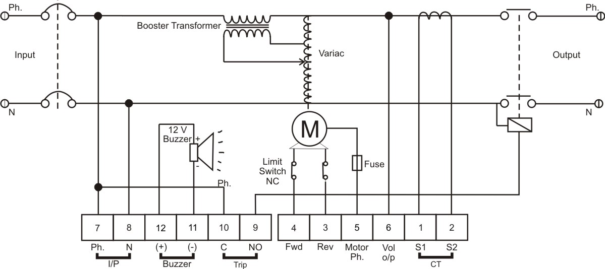
The BPS Servo Controller - Digital is a comprehensive metering and control solution designed for servo stabilizers, accommodating a wide range of input voltages and load requirements. This system minimizes production overheads such as wiring and testing, thereby enhancing...
Warning: include(partials/cookie-banner.php): Failed to open stream: Permission denied in /var/www/html/nextgr/view-circuit.php on line 713
Warning: include(): Failed opening 'partials/cookie-banner.php' for inclusion (include_path='.:/usr/share/php') in /var/www/html/nextgr/view-circuit.php on line 713