
servo motor control with microcontroller

The servo motor operates based on a feedback control system that ensures accurate positioning of the output shaft. The core components of a servo include the DC motor, control circuitry, a potentiometer, and a gear train. The control circuitry interprets the signal received through the control wire and adjusts the motor's operation accordingly. The potentiometer, connected to the output shaft, serves as a feedback mechanism by providing real-time information about the current angle of the shaft to the control circuitry.
The gear train amplifies the torque produced by the motor, allowing the servo to exert sufficient force to move the connected load. The design of the gear train can influence the speed and torque characteristics of the servo. For instance, a higher gear ratio results in increased torque but reduced speed, while a lower gear ratio produces higher speeds at the expense of torque.
Pulse Coded Modulation (PCM) is a key aspect of servo control. The servo interprets the duration of the pulse width to determine the target angle. The standard pulse width for neutral position is 1.5 milliseconds, with variations for other angles. For example, a pulse width of 1 millisecond typically corresponds to the minimum angle (0 degrees), while a pulse width of 2 milliseconds corresponds to the maximum angle (180 degrees). The servo's ability to maintain its position while receiving a continuous signal ensures precise control in applications such as robotics and aeronautics.
In summary, the servo motor's design and operation allow for precise control of angular motion through a combination of electronic signals, mechanical components, and feedback systems. The integration of these elements enables a wide range of applications, making servos essential in various fields, including robotics, automation, and remote-controlled devices.This shaft can be positioned to specific angular positions by sending the servo a coded signal. As long as the coded signal exists on the input line, the servo will maintain the angular position of the shaft. As the coded signal changes, the angular position of the shaft changes. In practice, servos are used in radio controlled airplanes to position control surfaces like the elevators and rudders. They are also used in radio controlled cars, puppets, and of course, robots. The guts of a servo motor are shown in the picture below. You can see the control circuitry, the motor, a set of gears, and the case. You can also see the 3 wires that connect to the outside world. One is for power (+5volts), ground, and the white wire is the control wire. So, how does a servo work The servo motor has some control circuits and a potentiometer (a variable resistor, aka pot) that is connected to the output shaft. In the picture above, the pot can be seen on the right side of the circuit board. This pot allows the control circuitry to monitor the current angle of the servo motor. If the shaft is at the correct angle, then the motor shuts off. If the circuit finds that the angle is not correct, it will turn the motor the correct direction until the angle is correct.
The output shaft of the servo is capable of travelling somewhere around 180 degrees. Usually, its somewhere in the 210 degree range, but it varies by manufacturer. A normal servo is used to control an angular motion of between 0 and 180 degrees. A normal servo is mechanically not capable of turning any farther due to a mechanical stop built on to the main output gear. The amount of power applied to the motor is proportional to the distance it needs to travel. So, if the shaft needs to turn a large distance, the motor will run at full speed. If it needs to turn only a small amount, the motor will run at a slower speed. This is called proportional control. How do you communicate the angle at which the servo should turn The control wire is used to communicate the angle.
The angle is determined by the duration of a pulse that is applied to the control wire. This is called Pulse Coded Modulation. The servo expects to see a pulse every 20 milliseconds (. 02 seconds). The length of the pulse will determine how far the motor turns. A 1. 5 millisecond pulse, for example, will make the motor turn to the 90 degree position (often called the neutral position). If the pulse is shorter than 1. 5 ms, then the motor will turn the shaft to closer to 0 degress. If the pulse is longer than 1. 5ms, the shaft turns closer to 180 degress. 🔗 External reference
Related Circuits
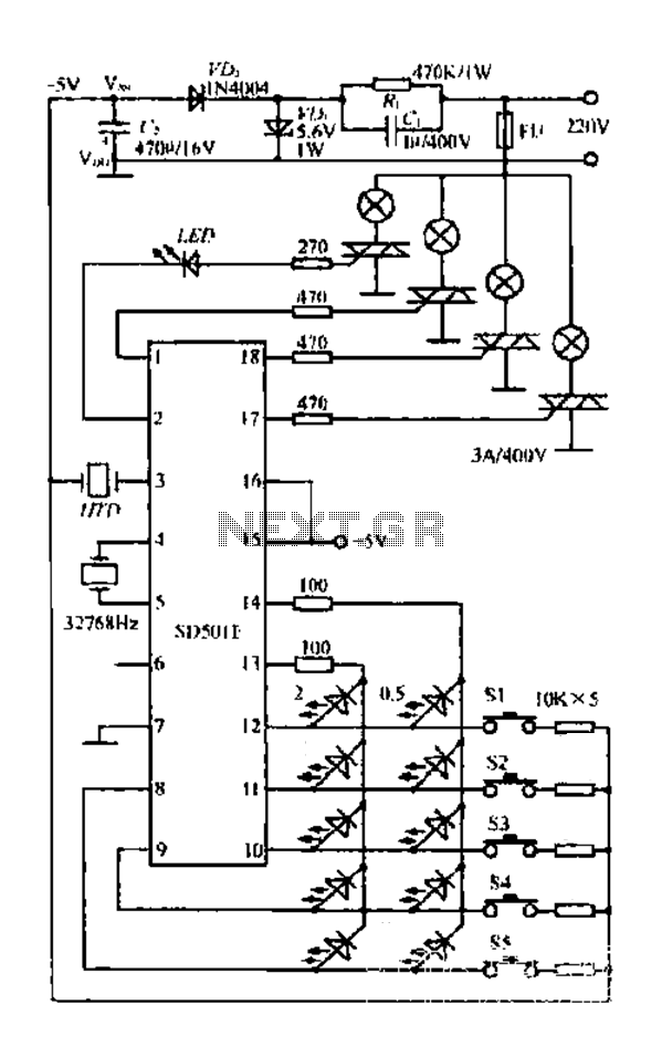
The FIG SD501E is a J tie fan integrated circuit (IC) characterized by progressive timing and three operational modes: strong, medium, and weak. It features three types of output settings and includes an electrical swing mechanism. The device is...
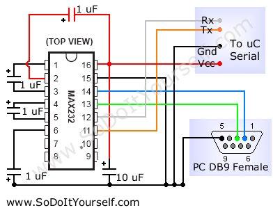
A device that provides a USB port is recognized as a "CP2103 USB to UART Bridge Controller" when connected to a Windows PC. According to the device documentation, it communicates in serial format at 38400 bps. The USB pinout...
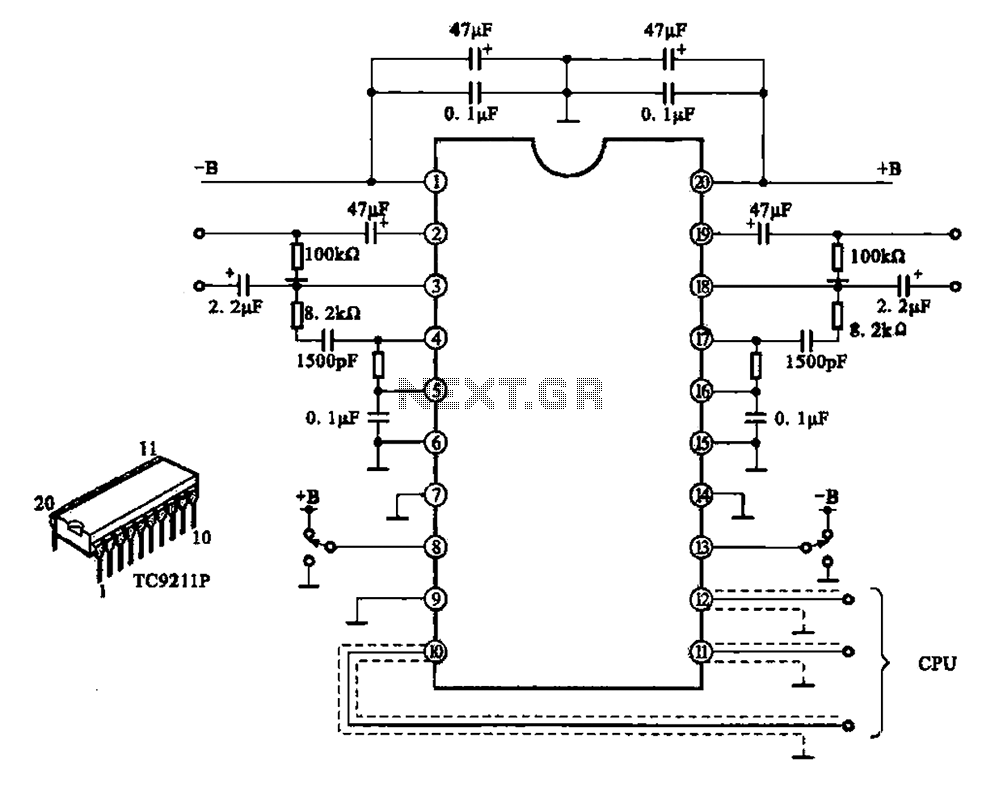
A typical electronic volume control circuit is commonly used in stereo audio devices connected through a computer (CPU). The circuit adjusts the volume of stereo signals via input and output pins. Control signals are sent to the CPU (including...
It's basically a photovore with a couple tactile sensors. It's rather complex but can give neat behaviors with modifications to the circuit. At this point I don't have any plans to give more information on this circuit so your...
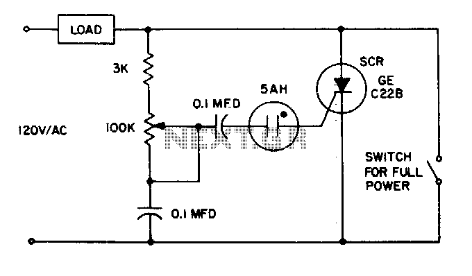
The 5AH will trigger when the voltage across the two 0 µF capacitors reaches the breakdown voltage of the lamp. Control can be obtained from full off to 95% of the half-wave RMS output voltage. Full power can be...
A switch that is controlled by its ambient temperature operates without human intervention, except during the assembly of the electronic thermostat. This thermally controlled switch has numerous practical applications. For instance, if the internal temperature of a computer rises...