
Communication between a USB/serial device and an AVR (atmega/Arduino) microcontroller
 microcontroller")
The device in question operates as a bridge between USB and RS232 interfaces, specifically utilizing the CP2103 chip, which is designed for converting USB signals to UART serial communication. The USB protocol involves four main connections: ground (GND), data positive (D+), data negative (D-), and power (VCC). The CP2103 manages the conversion of these USB signals into a format compatible with RS232, which typically includes transmit (TX) and receive (RX) lines along with ground.
In this application, the AVR-CDC project serves as a framework for implementing the CDC-232, which allows for the necessary signal conversion. The CDC-232 is essential in this setup as it translates the USB communication into RS232 signals. When programming the microcontroller to send data, it is crucial to ensure that the data rates and configurations match the expected parameters of both the CP2103 and the CDC-232. The expected baud rate of 38400 bps must be consistently maintained across all devices in the communication chain.
The observation of the signal on the oscilloscope indicates that the data transmission is successful up to the point of the CDC-232. However, the loss of the signal beyond this point suggests potential issues with the CDC-232 itself or its connection to the microcontroller. The absence of output on pins 4 and 5, where the USB signal is anticipated, may indicate a failure in the conversion process or a misconfiguration in the circuit setup. It is advisable to verify the connections, ensure proper power supply levels, and check for any possible shorts or miswirings in the circuit. Additionally, reviewing the firmware on the microcontroller for correct initialization and data handling routines is essential to resolve the communication issue.A device which provides a USB port. If I attach it to a Windows PC it is recognized as a "CP2103 USB to UART Bridge Controller". According to the device documentation, it should communicate in serial format at 38400bps. Since the USB pinout is different from the serial UART of the uC, firstly I thought I would need a circuit to convert thesignals. I found the AVR-CDC project and put on a CDC-232 in order to convert USB (GND, D+, D-, VCC) to RS232 (TX, RX, GND): I programmed my uC to send some data to the device and I can follow the signal with the oscilloscope until it enter into the CDC-232, then I lose it. I have no output on pins 4 and 5 of the CDC-232 uC, where I should have a USB signal. 🔗 External reference
Related Circuits
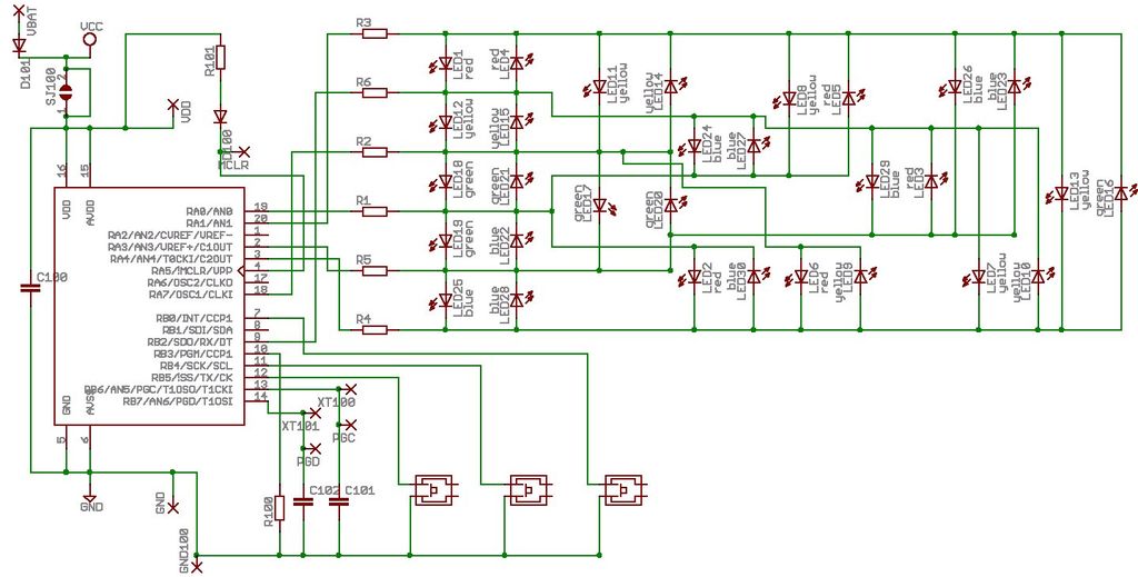
Microdot - wrist watch LED pattern timepiece. This project is a circuit board designed for creating a wristwatch-sized version. The Microdot wristwatch project involves the design and implementation of a compact circuit board that integrates LED technology to display time...
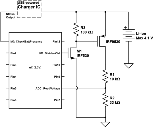
Currently using the PIC24FJ128GA010, there is a plan to utilize an Input/Output port to connect a 4.2 V LiPo battery and monitor the voltage to ensure it does not drop below 3.7 V. It is advised to avoid digital...
The schematic indicates that the AccelR8 utilizes only three integrated circuits (ICs). An AVR 8515 microcontroller performs the computational tasks and manages the other circuits. A MAX603 regulates voltage and controls the power-on and power-off functions. The key component...
Best Microcontroller Projects. Do you want to learn how to use a microcontroller in your electronic projects, or do you need inspiration for your next project? If so, you have found the right place! Here is a tutorial on...

Controlling devices using switches is common. Over the past few decades, remote control switches such as infrared remote control switches, wireless remote control switches, and light-activated switches have gained popularity. However, these technologies have their limitations. Laser beams can...
This article is intended for complete beginners with servo motors. It provides an overview of the basic theory behind servo motors and offers detailed instructions on how to utilize them with AVR microcontrollers such as the ATmega32. Servo motors are...