
Signal Detecting Auto Power-On Unit
To create a circuit that enables the activation of a sub-woofer or similar audio equipment via a signal, a simple relay-based design can be employed. The circuit operates by detecting a low-voltage control signal, which can be generated from various sources, such as a line-level audio output or a dedicated switch.
The core of the circuit consists of a relay, which acts as an electrically operated switch. When the control signal is applied, it energizes the relay coil, closing the normally open (NO) contacts and allowing the main power to flow to the sub-woofer. This approach provides a safe and effective means to control high-power audio equipment without directly interfacing low-voltage control signals with high-voltage circuits.
For the control signal, a transistor can be used to amplify the input signal if necessary. A resistor can be placed in series with the base of the transistor to limit current and prevent damage. Additionally, a diode should be connected in parallel with the relay coil to protect the circuit from back EMF generated when the relay is de-energized.
Power supply considerations should also be taken into account. The relay should be rated for the voltage and current of the audio equipment being controlled. A suitable power supply must be provided to ensure reliable operation of both the relay and the control circuit.
This relay-based activation circuit can be easily integrated into existing audio setups, providing a practical solution for remotely turning on sub-woofers or other audio devices without the need for complex modifications or additional equipment.How many times have you wished that there was a simple way to turn on that sub-woofer or some other piece of audio equipment, simply by sending it a signal? This ability is fairly common in commercial subs and some other gear, but there seems to be a complete absence of circuits on the net, and they seem completely unavailable as an add-on device.
🔗 External reference
Related Circuits
The wide variety of automotive motor drivers, including those used for HVAC (heating, ventilation, and air conditioning), headlamp, seat positioning, window, and mirror applications, necessitates circuits that perform more than just switching the motor on and off. The drivers...
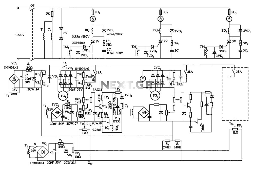
Collaboration with the dancers balanced bridge long on the porcelain unit. A sync adjustment rheostat speed control system is shown in Figure 3. The principle of speed control for electro-magnetic and photoelectric dancers is similar. The main motor (BQ2)...
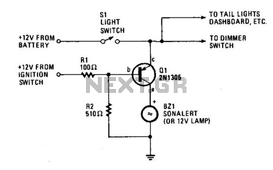
The circuit provides a visible or audible warning when the headlights are on. It utilizes a 2N1305 transistor as a switch to activate either a Sonalert tone generator or a small 12-V lamp. The operating current for the transistor...
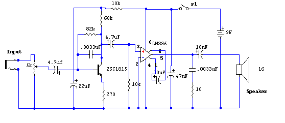
The primary component of this circuit is the LM386 amplifier chip. Additionally, it incorporates a transistor input to buffer the input signal and provide additional gain for the LM386. The LM386 is a low-voltage audio power amplifier capable of delivering...
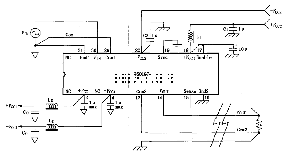
The basic connection circuit for the ISO107 signal and power supply is illustrated. Each power supply terminal must include a bypass filter. If the output current from the isolated power supply exceeds 15 mA, it is advisable to utilize...
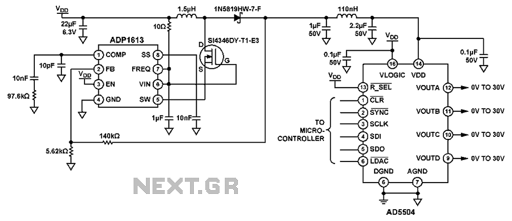
The circuit depicted in FIG. 1 generates a high-voltage signal for controlling the capacitance of barium strontium titanate (BST) capacitors. By applying voltages of V and 3V to the appropriate terminals, the capacitance of the BST can be modified....