
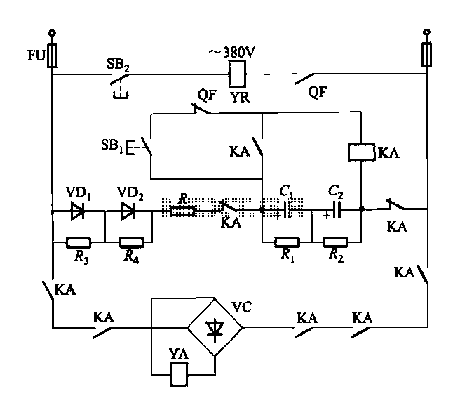
Multi-unit slip motor speed control system synchronous operation circuit

The described system incorporates a balanced bridge configuration that collaborates with dancers to achieve precise control of motor speeds within a porcelain unit. The sync adjustment rheostat plays a critical role in fine-tuning the speed control system, which is visually represented in the referenced figure. The electro-magnetic and photoelectric dancers operate under a similar principle, utilizing the main motor (BQ2) to establish a slip reference speed through its field winding.
The orientation of BQi and BQ3 is strategically designed to manage the slip of the motor's field winding effectively. The RPz potentiometer is essential for adjusting the overall speed of the system, allowing for flexibility in the operation of three motors simultaneously. Each motor's slip can be finely tuned, thanks to the integration of tachometer generators (TGi to TG3), which are connected to the electromagnetic slip clutch shafts of the respective motors.
The adjustment potentiometers (1RP1, 2RP1, 3RP1) are vital for modifying the negative feedback voltage associated with each motor's slip speed, providing a mechanism for dynamic speed adjustments. Furthermore, the sensitivity potentiometers (1RP2, 2RP2, 3RP2) allow for precise alterations to the slip speeds, enhancing the responsiveness of the system to changes in operational conditions.
The dish rheostats (RP., RPb) serve a crucial function in synchronizing the slip speeds of the three motors, ensuring that they operate in unison. This synchronization is vital for applications where coordinated movement is required, enhancing the overall performance and reliability of the system. The combination of these components creates a sophisticated speed control system that can adapt to varying operational demands while maintaining precise control over motor performance. Collaboration with the dancers balanced bridge long on the porcelain unit Sync adjustment rheostat speed control system shown in Figure 3 to 183 in FIG. Others, such as electro magnetic, photoelectric dancers speed control principle is similar. FIG, BQ2 main motor so that the slip (i.e., as a reference speed) of the field winding, BQi and BQ3 are oriented so that the slip of the front and rear of the motor slip motor field winding. RPz based order potentiometer, which can be adjusted to change the entire system (ie, three motor slip) speed.
TGi ~ TG3 for the three tachometer generator, they are connected with the respective electromagnetic slip clutch shaft of the motor. Adjust potentiometer 1RP1 (2RPi, 3RPl) can change the size of each slip motor speed negative feedback voltage (may cause speed changes).
lRP2 (2RP2,3RP2) the sensitivity potentiometer, which can be adjusted to change a corresponding slip speed of the motor. Dish rheostat RP., RPb to coordinate three slip speed of the motor, so that they run synchronously.
Related Circuits
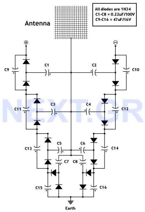
This circuit converts surrounding radio frequency waves to electric power. It can provide 40 Volts at 10 Watts indefinitely. The output power can be improved by adjusting the antenna. Placing the antenna near large metal objects increases power. The...
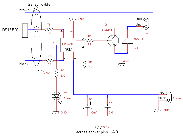
This is a fan controller designed for an audio/video cabinet. It utilizes a PICAXE 08M microcontroller and a DS18B20 temperature sensor. The fan activates at 30 degrees Celsius (approximately 86 degrees Fahrenheit) and deactivates at 28 degrees Celsius (around...
This circuit utilizes a 555 timer to control a 4017 decade counter. The outputs from the counter are used to drive transistor relay drivers. The duration for which the lights remain "on" can be adjusted by modifying the connections...
The DW15-200-630A breaker solenoid is a DC solenoid designed for short-time operation. The DK-1 control box utilizes an AC power switch to manage the electromagnet circuit, as depicted in Figure 6-7. The DK-1 type electromagnetic control box includes several...
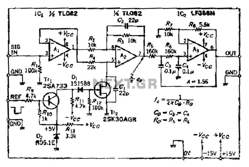
After turning off TT2, the input signal enters through chi Az, where the input resistance is very high and reaches the same potential. The inverting input terminal must also be associated with this movement. Therefore, Trr functions as a...
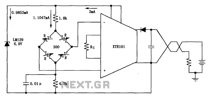
The circuit utilizes the LM129 voltage regulator to produce a 6.9V voltage reference, supplying a current of 1.0147mA from the 6.9V reference voltage to the bridge. The bridge may consist of varistor-type pressure sensors. The LM129 voltage regulator is a...