
Simple Battery Charger using LM350

The circuit operates effectively as a constant voltage source, utilizing the LM350 voltage regulator, which is known for its ability to maintain a stable output voltage under varying load conditions. The LM350 is configured to provide an output voltage that can be finely tuned between 13 V and 15 V through the use of potentiometer R6, allowing for customization based on specific application requirements.
Transistor Q1 (BD 140) plays a crucial role in temperature compensation; it acts as a temperature sensor that responds to changes in ambient temperature. The negative temperature coefficient of the output voltage is a result of the inherent characteristics of Q1, which decreases in voltage with increasing temperature. This is further amplified by the circuit configuration involving resistors R3 and R4, which influence the base current and, consequently, the behavior of Q1.
Transistor Q2 functions as a switch that ensures the battery does not discharge through resistor R1 when the mains power is not present, thereby protecting the battery and extending its life. The LED indicator provides a visual cue that mains power is available, enhancing the usability of the circuit.
Overall, this design effectively combines temperature compensation with voltage regulation, making it suitable for applications where stable voltage output is critical in varying temperature environments. The careful selection of components and their configuration allows for precise control over both the output voltage and the thermal behavior of the circuit.The circuit is designed as a constant voltage source with a negative temperature coefficient. The transistor Q1 (BD 140) is used as the temperature sensor. The transistor Q2 is used to prevent the battery from discharging through R1 when the mains power is not available. The circuit is designed based on the voltage regulator IC LM350. The output voltage of the charger can be adjusted between 13-15 V by varying the POT R6. The LM350 will try to keep the voltage drop between its input pin and the output pin at a constant value of 1. 25V. So there will be a constant current flow through the resistor R1. Q1 act here as a temperature sensors with the help of components R6/R3/R4 which more or less control the base current of Q1.
As the emitter/base connection of transitor Q1, just like any other semiconductor, contains a temperature coefficient of -2mV/ °C, the output voltage will also show a negative temperature coefficient. That one is only a factor of 4 larger, because of the variation of the emitter/basis of Q1 multiplied by the division factor of P1/R3/R4.
This results in approximately -8mV/ °C. The LED will glow whenever the mains power is available. 🔗 External reference
Related Circuits
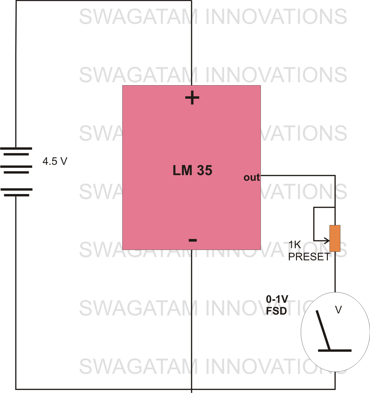
The circuit diagram provided illustrates a straightforward setup. There is no requirement for complex circuitry; simply connect a 0-1 V full-scale deflection (FSD) moving coil meter across the designated pins of the integrated circuit (IC). Adjust the potentiometer as...
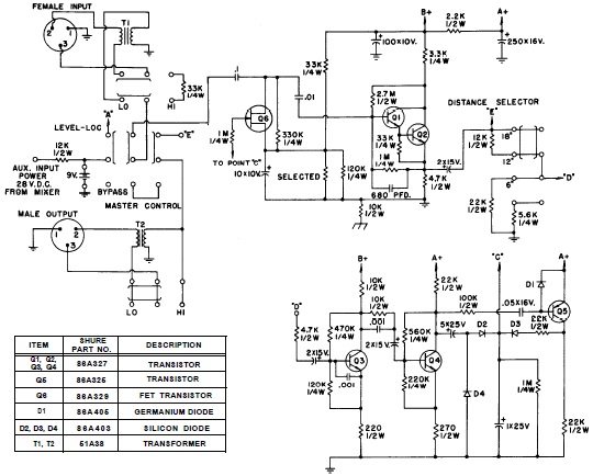
SHURE is an American corporation that manufactures consumer and professional audio electronics, including microphones, phonograph cartridges, and discussion systems. SHURE Incorporated is a well-established entity in the audio electronics industry, recognized for its innovative design and high-quality products. The company...
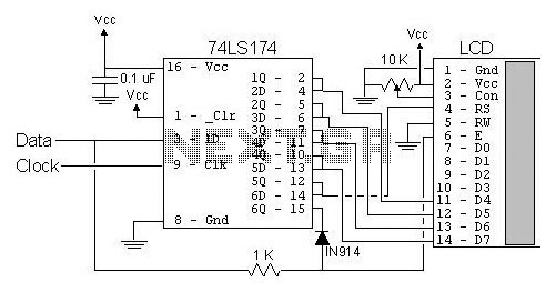
The most popular LCD interface is the Hitachi 44780 based LCD controller chip which provides a fairly easy to work with interface and low power consumption. The major drawback of the interface is the perceived complexity of working with...
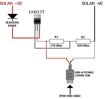
A solar charger for an iPod is no more difficult than creating a solar battery charger. Built-in iPod batteries operate at 3.7 Volts, with capacity (measured in mAh) varying by iPod model—e.g., 1,200mAh for a 2nd Gen, 850mAh for...
This project involves a mini USB car charger circuit that is simple to construct using only three components. The core of the circuit is the LM78M05 integrated circuit (IC), which is a 5V positive voltage regulator. This IC includes...
Build-in charger for instruments powered by single lithium-ion or Li-Pol accumulator. If external power supply not connected to charger, current back from the accu charger is very small. New version improved temperature stability and Not Needed NTC thermistor. After...