
Simple AM Radio Receiver circuit and explanation
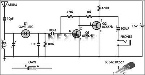
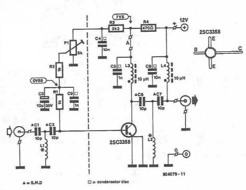
The described circuit operates as a basic yet effective radio receiver, utilizing an amplified crystal set design to enhance signal reception. The inductor, typically a ferrite rod, serves as an antenna, capturing AM radio signals. The tuning capacitor, which is adjustable, allows for fine-tuning of the frequency to isolate specific radio stations.
Diode D1 acts as a detector, converting the RF signal into an audio signal. The choice of a germanium diode is crucial, as it ensures optimal performance with low-voltage signals, which is common in crystal radio applications. Following detection, the output signal undergoes filtering to remove any residual RF components, ensuring that only the audio signal is passed on.
The audio signal is then amplified using a two-transistor stage, which provides sufficient power to drive low-impedance headphones, specifically those rated at 32 ohms, similar to those used in portable music players. This amplification stage is essential for achieving adequate sound levels, making the circuit suitable for personal listening experiences.
Overall, this circuit exemplifies a straightforward approach to AM radio reception, integrating essential components for signal detection and amplification while emphasizing efficiency and performance in low-signal environments.This circuit is essentially an amplified crystal set. The inductor could be a standard AM radio ferrite rod antenna while the tuning capacitor is a variable plastic dielectric gang, intended for small AM radios. The aerial tuned circuit feeds diode D1 which functions as the detector. A germanium type is far preferable to a silicon signal diode bec ause its lower forward voltage enables it to work with smaller signals. The detected signal from the diode is filtered to remove RF and the recovered audio is fed to a 2-transistor stage which drives a set of 32O phones from a Walkman-style player. Disclaimer All files are found using legitimate search engine techniques. This site does not and will not condone hacking into sites to create the links it list. We will and do assume that all links found on the search engines we use are obtained in a legal manner and the webmasters are aware of the links listed on the search engines.
If you find a URL that belongs to you, and you did not realize that it was "open to the public", please use the report button to notify the blogmaster of your request to remove it or it will remove within 24 hours. This is not an invitation for webblog haters to spam with requests to remove content they feel that is objectionable and or unacceptable.
Proof of URL ownership is required. NOTICE: This Blog Has Already Been Reviewed And Accepted By Blogger. com 🔗 External reference
Related Circuits
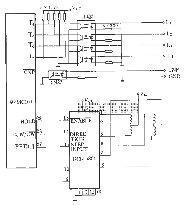
The PPMC external UChl 5804 demonstrates a four-phase stepping motor drive integrated circuit (IC) that is depicted in a downward motion. It utilizes the P-OUT, counterclockwise (ccw) / clockwise (cw), and HOLD outputs. The UCN5804 pins 9 and 10...
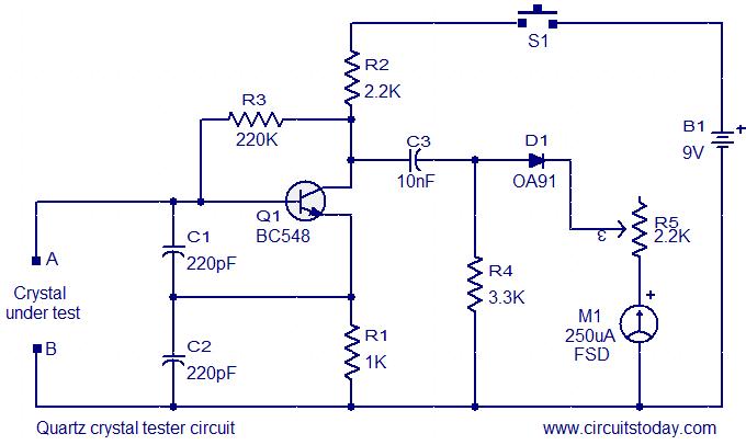
This is a straightforward and cost-effective circuit designed for testing quartz crystals. A Colpitts oscillator is employed using transistor T1. When the crystal is connected between terminals A and B, the circuit generates high-frequency oscillations. These oscillations will only...
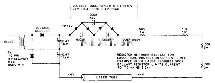
This circuit delivers a peak voltage of 10 kV, while limiting the current to 7.5 mA at 2 kV. The resistors included in the design serve the purpose of ballasting. Additionally, the starting circuit is unable to sustain the...
This UHF amplifier circuit project is beneficial for enhancing weak TV signals. The amplifier provides a gain of 10-15 dB within a frequency range of 400 to 850 MHz. To ensure optimal performance and reliability, the PCB tracks should...
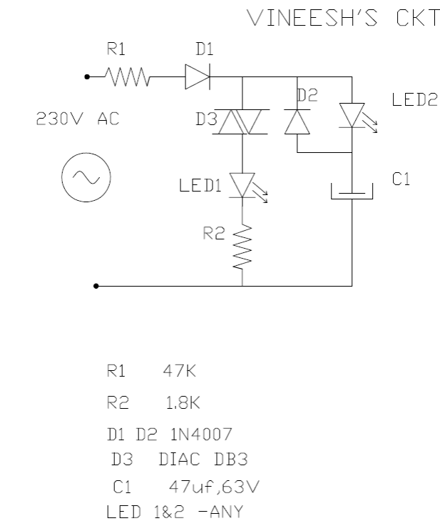
The following mains-operated LED flasher circuit, which is essentially an astable multivibrator circuit, utilizes a diac and resistor arrangement to achieve an interesting wig-wag flashing effect with two LEDs. The circuit was shared by Mr. Vineesh, a dedicated follower...
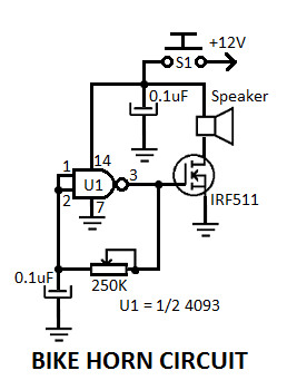
This simple electronic bicycle horn circuit utilizes a single gate from a 4093 quad 2-input NAND Schmitt trigger (U1) connected in a straightforward, low-frequency square wave configuration. The electronic bicycle horn circuit operates by generating a square wave signal that...