
simplest mains operated led flasher
The mains-operated LED flasher circuit functions as an astable multivibrator, leveraging the properties of a diac and resistive components to produce a visually appealing alternating flash in two LEDs. The circuit operates on the principle of capacitor charging and discharging, which is critical for achieving the desired blinking effect.
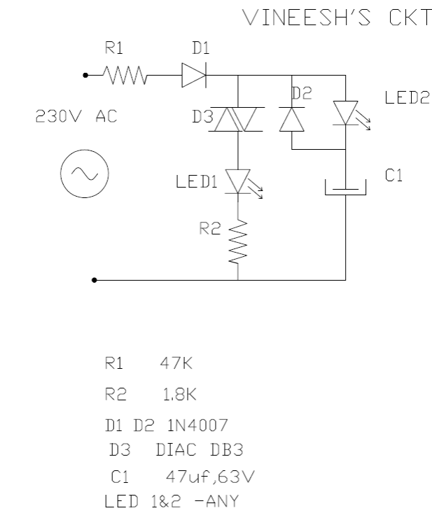
In this configuration, the capacitor charges through a resistor, with LED2 illuminating during the charging phase. The voltage across the capacitor rises until it reaches the breakdown voltage of the diac (DB3), which typically is around 30V. At this point, the diac switches on, allowing current to flow through LED1, which lights up, while LED2 dims as the capacitor discharges through the 1N4007 diode.
The use of a 1N4007 diode ensures that the discharge path is efficient and prevents reverse current flow, which could damage the circuit. The timing of the LED alternation can be adjusted by varying the resistor and capacitor values, allowing for customization of the flashing frequency. This circuit design is particularly suitable for applications requiring low-cost visual indicators or decorative lighting, providing a reliable and effective solution for alternating LED operation.
The schematic for this circuit would typically include a mains power input, a resistor connected to the capacitor, the diac in series with LED1, and the discharge path through the 1N4007 diode connected to LED2. Proper component selection and layout are essential to ensure safe and effective operation, particularly when working with mains voltages.The following mains operated LED flasher circuit which is actually an astable multivibrator circuit utilizes only a diac and resistor arrangement for implementing interesting wig wag flashing of two LEDs. The circuit was shared with me by Mr. Vineesh, who is one of the keen followers of this blog. I would like to present the email that was sen t to me by Mr. Vineesh. hope you remember me. i am not an electronics engineer, working as manager in a company, dealingbasically with Tool & Die Enggr, but self studying electronics for past 12-13 years, and have designed and made many simple projects of my own. some of them are marketed too. actually this entire ckt attached is not my idea. i have gone thru 230V blinking LED circuit in some sites. i just converted it to alternate blinking. ckt working fine for last 2-3 months continuously. (used green bright leds) i know very well no need to explain the working of ckt. but just given 2 lines because if i am wrong in theory, you can correct me. practically crkt is working well. while cap charging, led2, (series with cap) lights. DB3 get less than 30V while cap charging and does not conduct. after full charge of cap, diac conducts and led1( series to diac) lights, n cap discharge thru 1N 4007, that time LED2 light get dim, which gives alternate blinking effect.
all my ckts are drawn in note books, just selected one small ckt from that which is easy to draw in CAD & and convert pdf bcoz don`t want to send shabby hand drawn drawings. 🔗 External reference
Related Circuits

This circuit can switch two or more devices on and off in response to a series of rapid handclaps. The claps are detected by an electret microphone and amplified by a 741 operational amplifier (IC1). IC1 is configured as...
The project involves installing LED strips in a car's tail lamps to replace conventional bulbs. The required lengths for the LED strips are 16 inches, 15 inches, and 14 inches to fit properly within the housings. The selected LED...

This sound-operated switch detects the ringing of a phone and activates a lamp accordingly. The amplified signal across resistor R2 reaches diode D1 through capacitor C2. The rectified audio signals create a negative bias for transistor Q2, a PNP...
A circuit was constructed based on an LED beating heart frame instructable, but it is not functioning as expected. There is also mention of a built LED sequencer. The LED beating heart circuit typically involves a microcontroller, such as an...

A high-quality QRP transmitter, named NEXUS 6, is designed to explore issues related to extremely narrow bandwidth communication. This device is not merely a simplified version of a QRP transmitter; it aims to create a cost-effective system that can...

This project involves creating an RGB LED-lit love heart controlled by a PIC12F683 microcontroller. The design serves as a gift for a 15th wedding anniversary. The heart is crafted from a 200x150x6mm sheet of plexiglass, which is cut and...