
simple and cheap dark detecting led

The circuit begins with a basic LED configuration, similar to that of an LED throwie, where the LED is directly powered by a 3V lithium coin cell. The phototransistor is then integrated to detect light levels, controlling the transistor that activates the LED. Under light conditions, the phototransistor conducts up to approximately 1.5 mA, reducing the voltage across the resistor by 1.5 V, which deactivates the transistor and subsequently the LED. In darkness, the transistor allows approximately 15 mA to flow through the LED, resulting in a significant reduction in current consumption when the LED is off. It is important to note that the circuit utilizes a red LED due to the voltage drop across the transistor, which limits the voltage available to the LED to less than the full 3V. This voltage is marginal for powering blue LEDs; however, alternative methods such as using a low-cost FET may provide a solution for different LED types.
Assembly of the circuit can be performed on a breadboard, although creating a compact and deployable version is often more rewarding. The first step involves preparing the transistor and resistor. The 2N3904 transistor's pins are designated as Emitter, Base, and Collector when viewed from the front with the text readable. The resistor should be soldered between the Base and Collector leads of the transistor, ensuring proper orientation during assembly.How do you make an LED turn on when it gets dark. You might call it the "nightlight problem, " but the same sort of question comes up in a lot of familiar situations- emergency lights, street lights, silly computer keyboard backlights, and the list goes on. Solutions Lots. The time-honored tradition is to use a circuit with a CdS photoresistor, sometimes called a photocell or LDR, for "light-dependent resistor. " (Circuit Example 1, Example 2. ) Photoresistors are reliable and cost about $1 each, but are going away because they contain cadmium, a toxic heavy metal whose use is increasingly regulated. There are many other solutions as well. Look here for some op-amp based photodetector circuits with LED output, and check out some of the tricks used in well-designed solar garden lights, which include gems like using the solar cell itself as the sensor.
(Our own solar circuit collection is here. ) In this article we show how to build a very simple- perhaps even the simplest- darkness-activated LED circuit. To our LED and battery we add just three components, which cost less than thirty cents altogether (and much less if you buy in bulk).
You can build it in less than five minutes or less (much less with practice). What can you do with such an inexpensive light-controlled LED circuit Almost anything really. But, one fun application is to make LED throwies that turn themselves off in the daytime to save power. Throwies normally can last up to two weeks. Adding a light-level switch like this can significantly extend their lifetime. Here are our components: On top: a CR2032 lithium coin cell (3 V). On the bottom (L-R): the LED, an LTR-4206E phototransistor, a 2N3904 transistor, and a 1 k resistor. This LED is red, blindingly bright at 60 candela, in a 10 mm package. It casts a visible beam, visible for about twenty feet in a well-lit room. We got the LEDs and batteries on eBay, and the other parts are from Digi-Key, but Mouser has them as well.
As we mentioned, the last three cost about $0. 30 all together, and much less in bulk. The LTR-4206E is a phototransistor in a 3mm black package. The black package blocks visible light, so it is only sensitive to infrared light- it sees sunlight and incandescent lights, but not fluorescent or (most) discharge lamps- it really will come on at night. Our starting point is the simplest LED circuit: that of the LED throwie, which has an LED driven directly from a 3V lithium coin cell.
(Funny looking example here. ) From this, we add on the phototransistor, which senses the presence of light, and we use its output to control the transistor, which turns the LED on. When light falls on the phototransistor, it begins to conduct up to about 1. 5 mA, which pulls down the voltage at the lower side of the resistor by 1. 5 V, turning off the transistor, which turns off the LED. When it`s dark, the transistor is able to conduct about 15 mA through the LED. So, the circuit uses only about 1/10 as much current while the LED is off. One thing to note about this circuit: We`re using a red LED. That`s because the voltage drop across the transistor allows less than the full 3 V across the LED. The full three volts is really only marginal for driving blue LEDs anyway, so two-point-something really doesn`t cut it.
(Might be able to work around that with a cheap FET- haven`t tried yet. ) And now, let`s build it. You can certainly put this together on a breadboard, but there`s something more satisfying about the compact and deployable build that we walk through here. First get the transistor and the resistor. The pins of the 2N3904 are called (left-to-right) Emitter, Base, Collector, when viewing it from the front such that you can read the writing.
We`re going to solder the resistor between the leads of the Base and Collector of the transistor. Unusual part: hold the resistor with its leads at 90 degrees to those of the transi 🔗 External reference
Related Circuits
Most PC enclosures provide only a single LED to indicate hard disk access, with the LED being connected to the motherboard via a two-pin connector. However, this LED only works with IDE drives, and if a SCSI disk controller...
More: A comprehensive electronic schematic involves the representation of electrical components and their interconnections in a circuit. Each component is typically represented by standardized symbols, and the connections between them are depicted using lines. The schematic provides essential information...
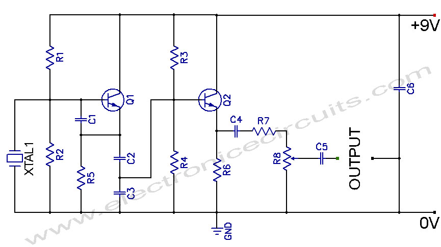
Crystal Controlled Oscillator Circuit. This general-purpose signal source is highly effective in signal-tracing applications. The output level is adjustable. The crystal-controlled oscillator circuit is designed to provide a stable and precise frequency output, which is essential for various electronic applications,...
This circuit is utilized for proximity detection and touch-controlled switching. When a finger approaches the sensor, it generates a capacitance to ground with a value ranging from 30 to 100 pF. Components involved include a resistor, capacitor, diode, and...
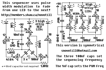
This deceptively simple sequencer actually pulse width modulates the LEDs as it fades from one LED to the next. Bulbs will last much longer when driven in this gentle manner. Add MOSFETs or transistors to the outputs if you...
The LM1036 is a DC-controlled circuit designed for adjusting tone (bass/treble), volume, and balance in stereo applications such as car radios, televisions, and audio systems. It features an additional control input that enables straightforward loudness compensation. Four control inputs...