Strange LED sequencer
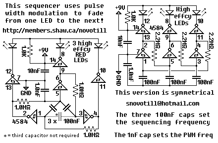
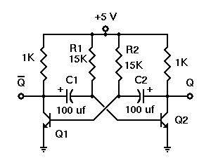
This deceptively simple sequencer actually pulse width modulates the LEDs as it fades from one LED to the next. Bulbs will last much longer when driven in this gentle manner. Add MOSFETs or transistors to the outputs if you wish to drive bulbs. You can reconfigure the three capacitors from a wye configuration to a delta configuration, or you can remove one of them entirely and the circuit will still function. Use high efficiency LEDs for best results. This circuit was inspired by the BEAM sequencer circuits on the web. I simply reversed the roles of the resistors-capacitors and floated the capacitors. If you remove the 1nF capacitor then the resulting monstrosity will chirp out RF interference as it hobbles along.
The described circuit operates as a sequencer that utilizes pulse width modulation (PWM) to control the brightness of LEDs in a fading pattern. The gentle modulation allows for a longer lifespan of the LEDs compared to direct drive methods. The circuit's design accommodates the use of MOSFETs or transistors, which can be added to increase the output current capacity, enabling the control of larger bulbs or higher power LEDs.
In terms of configuration, the circuit features three capacitors that can be arranged in either a wye (Y) or delta (Δ) formation. This flexibility allows for adjustments based on desired performance characteristics or component availability. The ability to remove one of the capacitors without disrupting the functionality of the circuit adds to its versatility, making it adaptable for various applications.
The choice of high-efficiency LEDs is recommended to optimize performance, particularly in terms of brightness and energy consumption. The inspiration drawn from BEAM (Biology, Electronics, Aesthetics, and Mechanics) sequencer circuits indicates that this design incorporates principles of simple, low-power electronics, often used in robotics and light displays.
The circuit's operation is influenced by the arrangement and values of the resistors and capacitors, which dictate the timing and behavior of the LED fading sequence. Notably, if the 1nF capacitor is removed, the circuit may produce unintended radio frequency (RF) interference, indicating that this component plays a crucial role in stabilizing the circuit's operation and preventing noise generation.
Overall, this sequencer circuit presents a practical solution for creating visually appealing LED effects while maintaining efficiency and simplicity in design.This deceptively simple sequencer actually pulse width modulates the LEDs as it fades from one LED to the next. Bulbs will last much longer when driven in this gentle manner. Add MOSFETs or transistors to the outputs if you wish to drive bulbs. You can reconfigure the three capacitors from a wye configuration to a delta configuration, or you can remove one of them entirely and the circuit will still function.
Use high efficiency LEDs for best results. This circuit was inspired by the BEAM sequencer circuits on the web. I simply reversed the roles of the resistors-capacitors and `floated` the capacitors. If you remove the 1nF capacitor then the resulting monstrosity will chirp out RF interference as it hobbles along. 🔗 External reference
