
Simple Cat.5 Network Tester
The network tester circuit utilizes a compact design that leverages the 4011 quad NAND gate IC, which provides both flip-flop functionality and clock generation capabilities. The RS flip-flop configuration allows for stable operation of the oscillator, which is critical for cycling through the test sequences. The clock oscillator's frequency can be adjusted by varying the capacitor and resistor values, enabling customization based on user requirements.
The 4017 decade counter is pivotal in this circuit, as it sequentially activates the corresponding LEDs and tests the network lines. Each output pin of the 4017 connects to a specific test line in the RJ45 connector, allowing for systematic testing of each pair. The logic of the circuit ensures that when an output is high, the corresponding LED lights up, providing immediate visual feedback on the status of the cable under test.
In terms of diagnostics, the circuit's design enables quick identification of faults within the network cable. The illumination of multiple LEDs indicates shorts between pairs, while the absence of light in the test LED signifies an open circuit. This functionality is essential for troubleshooting network issues effectively.
The power management aspect of the circuit is noteworthy, as it is designed to operate with minimal power consumption when idle. The standby current of less than one microamp is particularly advantageous for battery-operated or portable applications, ensuring extended operational life without frequent battery replacements.
Overall, this network tester circuit is a practical solution for network diagnostics, allowing a single user to efficiently check cable integrity without the need for additional personnel. Its straightforward operation, combined with effective visual indicators and low power consumption, makes it a valuable tool for electronics engineers and network technicians alike.This circuit came from a need for a "quick and dirty" network tester that could be operated by one person. All the commercial units I tried required a person at the other end to check the remote LEDs, as the transmitters could not be made to cycle through the test continuously to allow one person to check both ends.
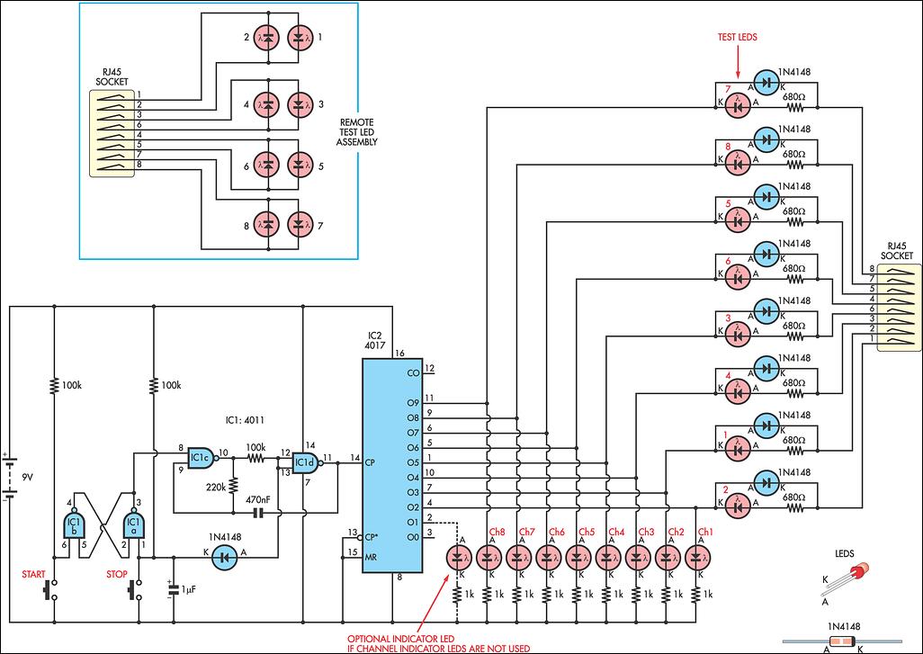
It must be noted that this unit will only check for pair continuity, pair shorts, crossed wires, and shorts to other pairs. It will not test bandwidth, etc. Operation is fairly basic. Half of the 4011 quad 2-input NAND gate is an RS flip-flop (IC1a, IC1b) which controls the other half, IC1c & IC1d, operating as a clock oscillator. You can either start and stop the oscillator running by pressing the Start and Stop switches or by virtue of diode D1 connected to pins 12 & 13, use the Stop switch to allow manual clocking of the 4017 counter.
The 4017 drives one of eight LEDs and the lines to the RJ45 socket. An output "High" on the 4017 decides which line is under test, and if the circuit is complete, the test LED`s current is "sunk" by the 4017 and the LED will light. If the corresponding test LED on the remote fails to light, then there is a short of that pair in the cable under test.
If more than one LED lights, it indicates a short with another pair. A dark test LED on the transmitter indicates that pair is open circuit. "Start" starts the circuit cycling at a rate determined by the 470nF capacitor and 220kO resistor and "Stop/Step" stops cycling, steps through the lines, and when stepped so that no channel LEDs are alight, effectively switches the unit off with a standby drain current of less than a microamp. 🔗 External reference
Related Circuits
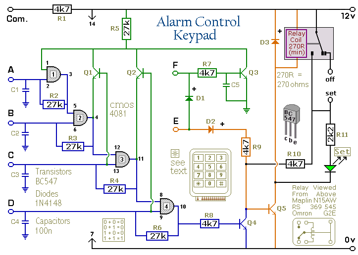
Pressing a single key on the keypad energizes the relay. Entering a four-digit code of your choice de-energizes the relay. The circuit was designed to control the Modular Burglar Alarm System but can have other applications. A five-digit version...
Simple circuitry suitable for moving-magnet cartridges. Passive high-frequency equalization. This simple but efficient circuit devised for cheap moving-magnet cartridges can be used in connection with the audio power amplifiers shown in these webpages, featuring low noise, good RIAA frequency...
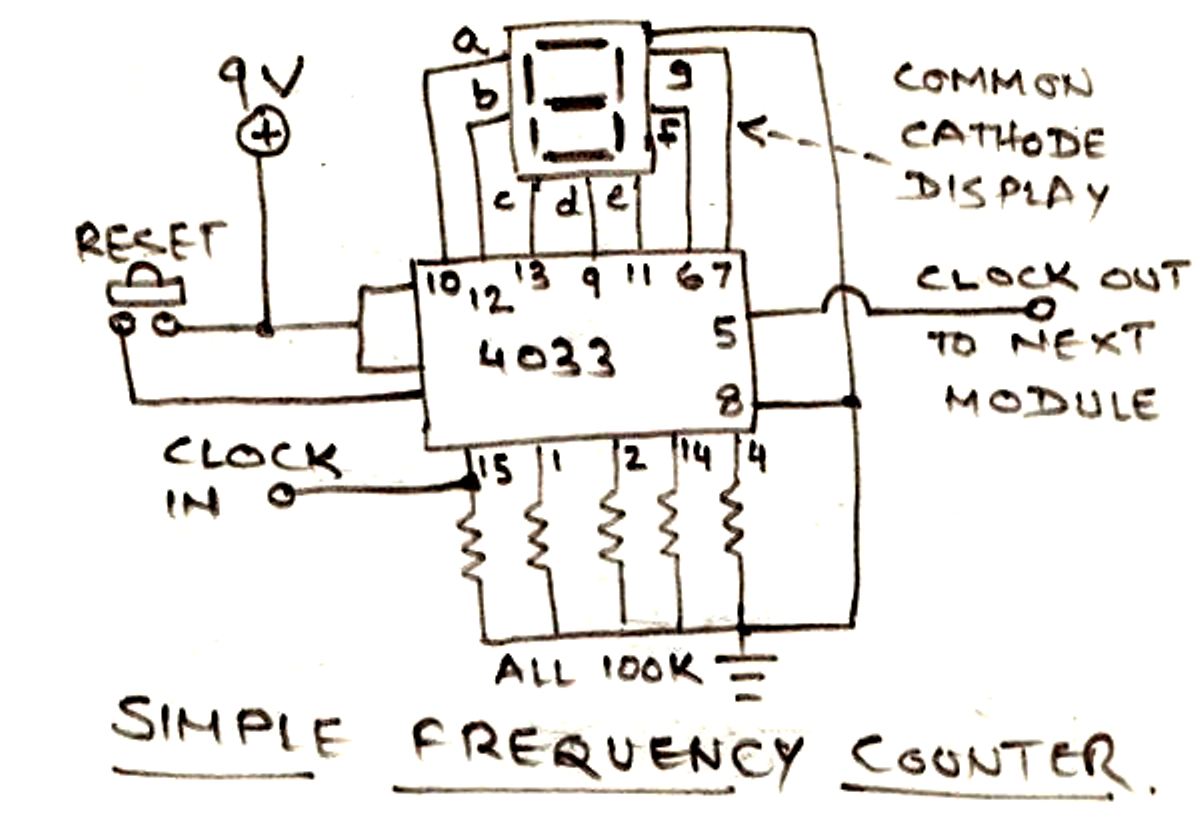
The circuit illustrated below is designed for measuring frequency in Hertz (Hz). It is straightforward to construct, utilizing a single IC 4033 and a common cathode display as the main components. For measuring higher frequencies, typically in the range...

The figure illustrates the circuit diagram of a multi-tone alarm, which fundamentally operates as an amplifier circuit. The core component of this circuit is the dual. The multi-tone alarm circuit is designed to produce various sound tones, enhancing its alerting...
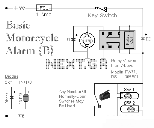
Two simple relay-based motorcycle alarm circuits. These are easy to build and can be used to protect motorcycles, but they also have many other applications. If relays with 6-volt coils are used... The motorcycle alarm circuits described consist of two...
A six-year-old child and an adult viewed a project on YouTube and captured an image of it using the print screen function to create a similar design. The project likely involves a basic electronic circuit that can be replicated easily,...