
Simple Phono Preamplifier

The described circuit is a passive high-frequency equalization circuit specifically tailored for moving-magnet cartridges, commonly used in vinyl record playback systems. The circuit is designed to ensure that the audio signal is processed with minimal noise and distortion, while maintaining a faithful reproduction of the RIAA (Recording Industry Association of America) frequency response curve, which is essential for accurate audio playback.
The circuit operates effectively over a frequency range of 1 kHz to 20 kHz, where it performs passive equalization. This is crucial for moving-magnet cartridges, which can exhibit different frequency response characteristics depending on the design and materials used. By employing passive components, the circuit achieves a balance between simplicity and performance, making it an economical choice for audio enthusiasts.
Key components include several resistors (R1 to R8) and capacitors (C1 to C3), which are selected to optimize the circuit's performance. The resistors are rated at 1/4W, ensuring they can handle the power levels typical in audio applications. The values of the resistors are as follows: R1 at 47KΩ, R2 at 100Ω, R3 at 6.8KΩ, R4 at 68KΩ, and both R5 and R6 at 2.7KΩ, with R7 at 2.2KΩ and R8 at 39KΩ. These resistors work together to set the gain and frequency response characteristics of the circuit.
Capacitors C1, C2, and C3, each rated at 100µF and 25V, play a vital role in coupling and decoupling signals, as well as filtering out unwanted noise. The use of electrolytic capacitors is common in audio circuits due to their ability to provide high capacitance in a relatively small package.
The circuit is powered by a dual ±18V supply, which is essential for op-amps used in audio processing. This voltage level enhances headroom, allowing the circuit to handle larger signal amplitudes without distortion. The choice of transistors and their configuration is critical in providing the necessary supply voltage while maintaining low noise levels.
Overall, this circuitry is an effective solution for users looking to enhance the performance of moving-magnet cartridges, ensuring high-quality audio output that meets the demands of modern audio systems.Simple circuitry suitable for moving-magnet cartridges Passive high-frequency equalization. This simple but efficient circuit devised for cheap moving-magnet cartridges, can be used in connection with the audio power amplifiers shown in these webpages, featuring low noise, good RIAA frequency response curve, low distortion and good high frequency transients behavior due to passive equalization in the 1 to 20KHz range. Transistors and associated components provide ±18V supply to the op-amp, improving headroom and maximum output voltage.
R1_________47K 1/4W Resistor R2________100R 1/4W Resistor R3__________6K8 1/4W Resistor R4_________68K 1/4W Resistor R5,R6_______2K7 1/4W Resistor R7__________2K2 1/4W Resistor R8_________39K 1/4W Resistor C1-C3_____100µF 25V Elect 🔗 External reference
Related Circuits
The Audio Research Corporation LS22 Line Stage Preamplifier was selected for this upgrade. The Audio Research LS22 Line Stage Preamplifier is a high-performance audio component designed to enhance the quality of sound reproduction in audio systems. This preamplifier features a...
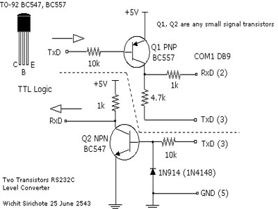
When connecting a microcontroller project to a COM port on a PC, an RS-232 converter is required. Various chips can accomplish this task, such as the MAX232 and DS275. However, for a simple and cost-effective RS-232 converter, the following...
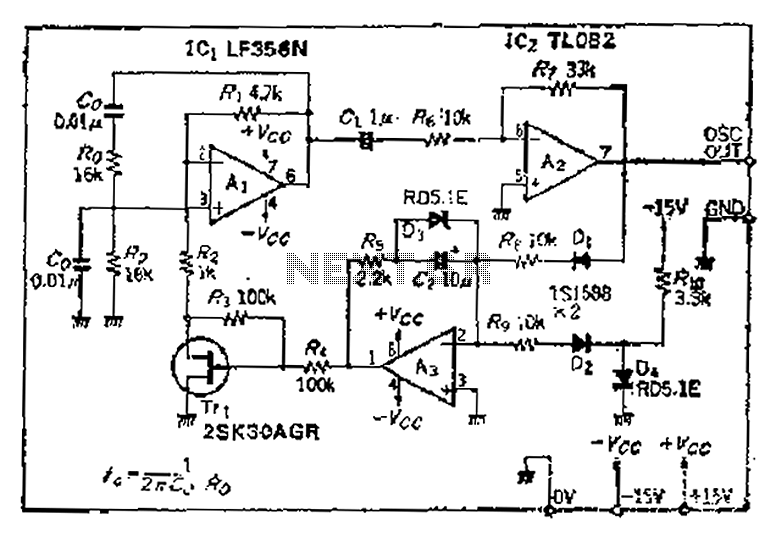
The intermodal servo preamplifier circuit operates at 115V and 60Hz, designed to provide a differential output for a servo motor amplifier. It features an inverting connection using an operational amplifier (op-amp), along with an additional op-amp configured to create...
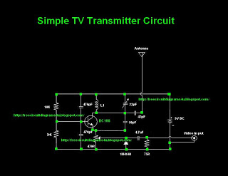
Many individuals inquire about TV transmitters. This document provides a useful circuit diagram that enables signal transmission over distances of 75 to 100 meters. The circuit diagram is not original but was provided by a colleague. Contributions of circuit...
The preamp featured is very straightforward to make on the PCB, and has an innovative tone defeat function. Rather than completely disable the tone controls, they are massively de-sensitised, and when "defeated" have a maximum range as shown in...
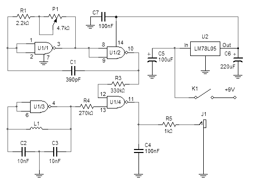
This simple metal detector requires only a handful of components and an evening's work. Built around a cmos4011 IC, is very robust and versatile. The 250 kHz reference oscillator is built with two gates (U1/1 and U1/2), C1, R1...