
Simple Cellphone Battery Charger Circuit

The battery-operated cell phone charger circuit leverages the voltage regulation capabilities of the IC 7805, which is a popular linear voltage regulator. This IC is capable of providing a stable output voltage of 5 volts, which is essential for charging most modern cell phones. The design requires minimal additional components, typically comprising a few resistors and capacitors that help stabilize the output and filter any noise from the input voltage source.
The input voltage to the circuit is sourced from a lead-acid or SMF battery, which can deliver a maximum of 35 volts. This high input voltage is reduced to a safe and usable level by the 7805 regulator. The current-limiting resistor is a crucial component in this setup, as it protects the circuit from excessive current that could potentially damage the IC or the device being charged.
In practical applications, the output from the IC is connected to the charging pin of the cell phone, ensuring compatibility with the device's charging requirements. It is important to ensure that the connections are secure and that the polarity is correct to prevent damage to the cell phone.
Overall, this circuit exemplifies the efficiency and simplicity that modern integrated circuits bring to electronic design, allowing for effective solutions to everyday problems such as charging mobile devices. The straightforward nature of the design makes it accessible for hobbyists and professionals alike, emphasizing the significant advancements in circuit design facilitated by integrated technology.With the advent of modern ICs, sophisticated circuits today no longer have to be complex and lengthy. The chips themselves carry most of the complex circuitry built-in and single handedly perform the desired function.
Take for example the present battery operated cell phone charger circuit, which is intended for a relatively application of chargin g a cell phone battery yet can be simply built using just a couple of passive parts along with a single active part (the IC 7805). Yes indeed, if you build the circuit which is shown, exactly as per the guidelines of the schematic, completing and getting rewarded through its service won`t be difficult at all.
The input (max 35 volts) from any automobile lead acid or SMF battery is applied to the input of the circuit, instantly a regulated 5 volt output is obtained at the respective terminal of the IC via the current limiter resistor. The output must be terminated through an appropriate charging pin as used in most of the AC operated cell phone chargers.
🔗 External reference
Related Circuits
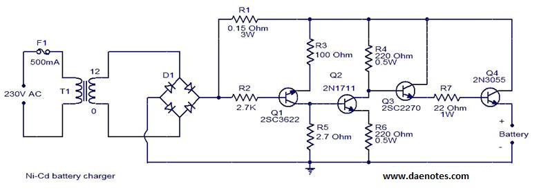
This circuit is primarily designed for charging 12V Ni-Cd battery packs. However, it can also be used to charge 6V and 9V battery packs with slight modifications. The circuit operates by utilizing a power supply that provides the necessary voltage...
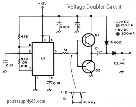
The schematic diagram originates from a 12V DC voltage doubler circuit power supply. This circuit diagram illustrates a DC voltage doubler/DC converter that transforms a 12V DC power supply into 24V DC and 18V DC outputs. It is compatible...
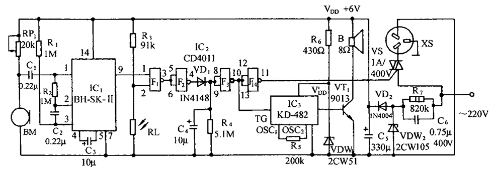
The circuit illustrated includes a sound transducer sensing switch, an electrical light control switch, an SCR control circuit, a vocal music circuit, and an AC step-down rectifier circuit. The circuit comprises several interconnected components that serve distinct functions, allowing for...
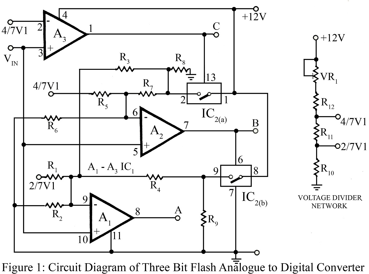
The flash type converter is the simplest and fastest type of analog-to-digital converter. The entire digital output word is available immediately after the propagation delay time of the comparators and the encoding logic gates. A typical conversion time for...
The project described in this article is a constant Q, fully expandable graphic equaliser. Where most "conventional" graphic EQ circuits have a Q that is dependent on the setting of the pot, this one maintains the same Q at...
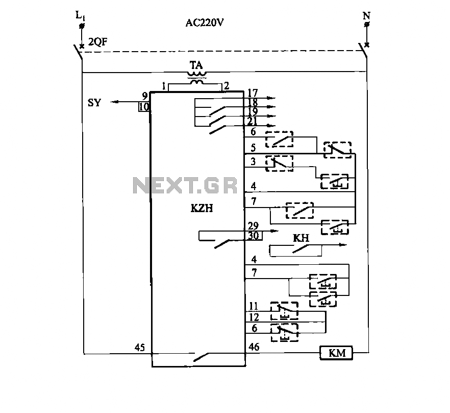
It utilizes the SHD series of electronic control equipment modules. The fan control box KZH functions as the HKD 1F electronic module. The SHD series of electronic control equipment is designed for various applications, including fan control systems. Within this...