
Simple Characterization Circuit for Rechargeable AA Cells
The characterization circuit is designed to provide a comprehensive analysis of rechargeable AA cells, ensuring accurate measurements of both capacity and output resistance. The integration of the DS2756 IC allows for precise monitoring of the cell's voltage and current throughout the discharge cycle. The use of a USB interface simplifies the connection to a PC, facilitating easy data logging and analysis without the need for an external power supply. The software interface enhances user interaction, allowing for straightforward initiation of measurements and easy access to logged data. The calibration process ensures that the system maintains accuracy over time, accommodating variations in the sense resistor and ensuring reliable readings. This system is particularly valuable for applications where battery performance is critical, enabling users to assess the health and capacity of rechargeable AA cells effectively.This characterization circuit, plus a PC and some software, accurately measures the full discharge cycle for a rechargeable AA cell. Cell capacity and output resistance can easily be determined from the curve resulting from these measurements.
Rechargeable AA cells are very popular for a large variety of portable applications. The number of brands is also high and the cell quality can differ considerably. Cell capacity is sometimes different from that specified, and the capacity often deteriorates dramatically after a limited number of discharge cycles. The proposed characterization circuit, in combination with a PC and AA-Cell Characterizer software, can accurately measure a full discharge cycle.
From the resulting curve you can easily determine the cell capacity and output resistance. The circuit is built around an IC intended for fuel-gauging applications in battery packs ( DS2756 ). The DS2756 provides the key components necessary to accurately estimate remaining battery-pack capacity by integrating low-power precision measurements of temperature, voltage, current, and current accumulation (integral of current).
This hardware can also record the discharge cycle of a single AA cell (either NiCd or NiMH ) with accuracy. In Figure 1, the simple circuit is connected to the USB port of a PC. No external power source is required because power is extracted from the USB bus voltage. U1 ( DS9490R ) is a USB dongle that converts the USB protocol to the 1-Wire ® protocol, thereby allowing the PC to communicate with the key circuit component (U2).
U2 measures the cell voltage on pin 1 (VIN) through R1, the cell current through R4, a 25m © sense resistor connected to pins 7 (SNS) and 2 (VSS). The programmable I/O at pin 3 (PIO) allows PC software to control the gate of Q1. When PIO is high, Q1 switches on and loads the cell with R2. That connection causes a discharge current of approximately 1A. When PIO is low, Q1 switches off and removes the cell load. Diode D1 is required to lower the 5V USB voltage to keep VDD below the maximum allowed voltage of 4. 5V. The AA-Cell Characterizer software, written in Visual Basic, performs the cell discharge cycle. (Note: please see Drivers and Additional Software below before installing this software. ) This software initializes U2 and switches off Q1. When you insert a fully charged cell, the software indicates the measured cell voltage (Figure 2a). After you click "Start Measurement, " the software switches on Q1 and then logs the cell voltage and current every second.
After each logged point, Q1 switches off shortly to allow measurement of the unloaded cell voltage, which is also logged (Figure 2b). To prevent cell damage, the measurement is stopped automatically when the cell voltage drops below a certain limit.
This limit can be modified and is stored in the EEPROM memory of the DS2756. The value defaults to 800mV. After a measurement has been stopped, the "Accumulated Current" field shows how much charge has been drawn from the cell and indicates the actual cell capacity. The measurement can also be stopped manually by clicking the "Stop Measurement" button. Clicking "Save Data" saves the logged data to disk for further analysis. Since the sense resistor is very small, there can be some variation due to soldering connections. The resistor value used by the software can be adjusted for calibration. To calibrate the resistor, first start the software. Next, bypass Q1 with an ampere meter connected between source and drain. Then connect a battery and monitor the current reported by the ampere meter and the software. Adjust the resistor value so that both values match. The new value is stored in the EEPROM memory for future measurements. The default value is 25. 00m ©. The measured data can be analyzed with a Microsoft ® Excel ® spreadsheet. You can import the log file by clicking "File" and "Open, " and then choose "All Fil 🔗 External reference
Related Circuits
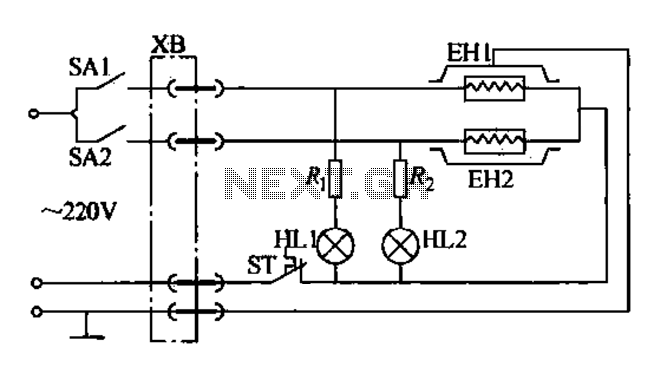
Currently, the use of cookers has become fashionable due to their speed, cleanliness, and low pollution levels, making them a favorite among consumers. Cookers circuit. The modern cooker circuit typically involves a combination of heating elements, control systems, and safety...
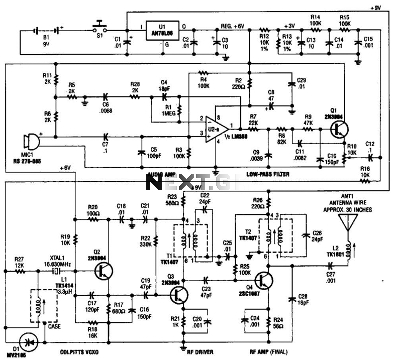
This tracking transmitter consists of four distinct subassemblies: a free-running multivibrator, a transmit switch, an audio-tone generator, and an FM transmitter. The multivibrator, which produces a pulse width with a pulse separation of 1500 ms, is built around Q1...
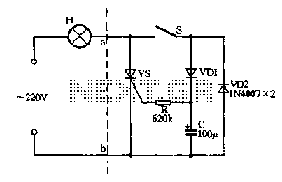
Closing the switch S allows the AC positive half-cycle to flow through diode VDI and resistor R, causing the SCR to open simultaneously at both ends of the capacitor C, which becomes fully charged. During this phase, the positive...

A capacitor step-down DC power supply circuit is presented. This circuit eliminates the need for power transformers, utilizing capacitive voltage drop rectification and regulation, which significantly reduces the overall size of the circuit. The circuit includes a capacitor step-down...
This ultra-bright white LED lamp operates on 230V AC with low power consumption. It is suitable for illuminating VU meters, SWR meters, and similar applications. The ultra-bright LEDs available in the market range from Rs 8 to 15. These...
This 5-volt Switch Mode Power Supply circuit utilizes an integrated circuit (IC) from National Semiconductor, which specializes in the production and design of ICs for switch-mode power supply applications. The 5-volt Switch Mode Power Supply (SMPS) circuit is designed to...
Warning: include(partials/cookie-banner.php): Failed to open stream: Permission denied in /var/www/html/nextgr/view-circuit.php on line 713
Warning: include(): Failed opening 'partials/cookie-banner.php' for inclusion (include_path='.:/usr/share/php') in /var/www/html/nextgr/view-circuit.php on line 713