
Novel delay lighting switch circuit
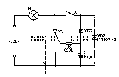
The described circuit utilizes a switch (S) to control the charging and discharging of a capacitor (C) in conjunction with a silicon-controlled rectifier (SCR) and diodes (VDI and VD2) to manage the flow of alternating current (AC) to a lamp (H). When the switch S is closed, the positive half-cycle of the AC voltage is directed through diode VDI and resistor R, allowing the capacitor C to charge. The SCR, once triggered, allows current to pass through to the lamp H, illuminating it during the positive half-cycle.
During the negative half-cycle, diode VD2 conducts, providing an alternative path for current to flow to the lamp H, ensuring that it remains powered. This dual-path operation allows the lamp to receive continuous power, even as the AC cycle alternates. When the switch S is opened, the capacitor C begins to discharge through the resistor R. The SCR remains conductive due to the discharge current, which sustains the light output from the lamp H. However, the interruption of the negative half-cycle by opening switch S leads to a reduction in the effective voltage across the lamp, causing it to dim.
The circuit's operation is dependent on the timing of the capacitor's discharge and the characteristics of the SCR, which requires a gate trigger current to remain conductive. As the capacitor discharges, the gate current diminishes until it reaches a threshold where the SCR can no longer sustain conduction. This occurs at the zero crossing of the AC voltage, resulting in the lamp H turning off.
This configuration is useful in applications where a controlled dimming effect is desired, allowing for gradual illumination and extinguishing of the lamp, enhancing user experience while managing power effectively. The design can be implemented in various lighting applications, providing both functionality and efficiency in AC-powered lighting systems.Closing the switch S, AC positive half cycle through VDI, R vs SCR opened simultaneously at both ends of the capacitor C is full charge. In this case the positive half cycle alternating current through the lamp H vs power, negative half-cycle through the
diode VD2 to the bulb H power, so in this case the lamp H total pressure supply. When you turn off the lights, turn on the switch S, the capacitor C discharges through the resistor R, the discharge current is maintained vs SCR continues to conduct, so light bulbs H in the positive half cycle of the current through the still, but because S cut off the negative half cycle of the power supply VD2 loop, so the lamp H in a semi-state voltage power supply, lamp dark light. About 1 minute after the capacitor C is discharged, the loss vs SCR gate trigger current at the zero crossing of the AC off, the lamp goes out.
Related Circuits

This is a circuit design for a doorbell that produces a bird-like sound. The circuit is controlled by an NPN transistor. The operation of the circuit begins when P1 is set to an experimental value, starting with approximately 220...
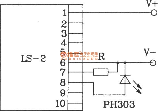
The LS-2 remote control switch infrared sensor module is similar to the LS-18 but functions as a reflector. The LS-2 pin diagram and internal block diagram provide insights into its electrical parameters. The operating voltage for the LS-2 remote...
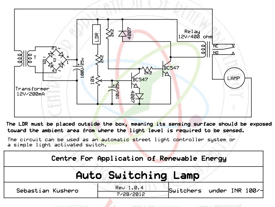
The light-activated switch circuit can be used for switching off a particular lamp or group of lamps in response to varying ambient light levels. The light-activated switch circuit utilizes a light-dependent resistor (LDR) as the primary sensing element to detect...
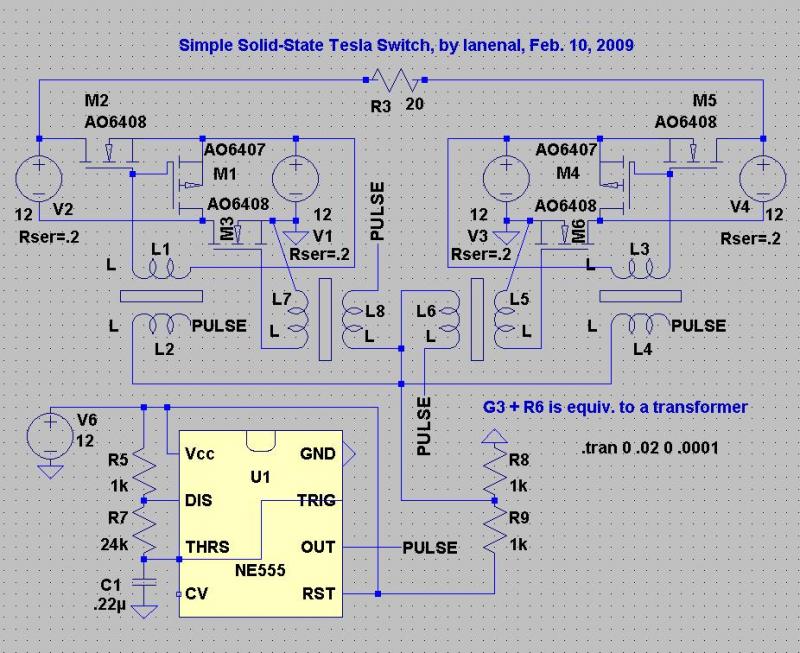
This circuit is designed for ease of tuning. When the pulse voltage reaches 6V, all transistors operate as open switches, eliminating the risk of battery shorts. The pulse voltage source V5 can be substituted with a 555 astable circuit....
There are two regulator circuits that utilize the L200 integrated circuit from SGS-Thomson to regulate voltage and current. In circuit Fig. 1, the output voltage can be adjusted using the variable resistor RV1. In Fig. 2, both output voltage...

Alarm system designs often require circuitry that can detect whether a phone line is active or broken. The primary challenge in this design is to draw less than 5 µA from the phone line, which operates within a voltage...