
SIMPLE CONTINUITY TESTER CIRCUIT

This simple continuity tester circuit is designed to provide an efficient means of verifying the integrity of electronic components and circuits. The circuit typically consists of a power source, an LED indicator, and a series of resistors to limit current and protect the LED from excessive current flow.
When testing a component, the user connects the terminals A and B to the leads of the component or circuit segment. The power source energizes the circuit, and if a continuous path is present, current flows through the LED, causing it to light up. The brightness of the LED can indicate the quality of the connection; a dim LED may suggest a high-resistance connection, while a bright LED indicates a low-resistance path.
In applications involving high impedance components, the circuit may incorporate a buffer stage or an operational amplifier to ensure that the testing process does not affect the component being tested. This is crucial for components like capacitors and transformers, where the testing circuit should not influence the component's behavior.
Overall, this simple continuity tester is an invaluable tool for electronics repair, allowing technicians to quickly diagnose faults and determine the operational status of various electronic components without the limitations imposed by traditional multimeters.This circuit have an advantage over ordinary CONTINUITY testing Device, usually we are using multimeter to check the continuity of a circuit. It is not suitable to check the continuity of a circuit with high Impedence or resistance like Transformer, Capacitors, and even for high value Resistors.
This circuit helps you to determine whether the devi ce or electronic component is working fine And by using this SIMPLE CONTINUITY TESTER you can repair any damaged electronic devices easily [By identifying the actual fault of the device]. Connect the terminals A and B to any electronic component or circuit which is to be tested. The LED will glow if the circuit having a continuous path or the component is working finely. Otherwise the LED remains OFF. 🔗 External reference
Related Circuits
This DC voltage doubler circuit generates a voltage that is double its supply voltage. It is beneficial when a higher voltage level is required from a single power source. The DC voltage doubler circuit typically employs a combination of capacitors...

A simple FM transmitter connects a home entertainment system to a portable radio that can be moved around the house and into the backyard. For instance, music can be played from a CD player in the living room and...
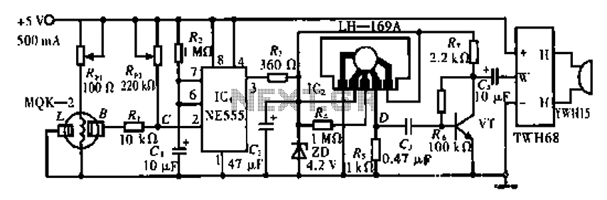
The circuit operates using the MQK-2 gas sensor, which detects the presence of combustible gases or smoke through surface adsorption. When gas is detected, the inter-electrode resistance (BL) decreases significantly. This change in resistance affects the voltage at node...

This is a fire alarm system utilizing the IC TD2002 suite to detect fire incidents. The alarm is crucial in residential complexes, allowing for early detection. It operates by detecting fog generated by fire, which reduces the light reaching...

Charging a mobile phone or cellphone battery presents a significant challenge while traveling, as a power supply source is often not readily available. If the cellphone remains switched on continuously, its battery can deplete within five to six hours,...

This is a simple 2N2222 transistor-based FM transmitter circuit that operates within the FCC (Federal Communications Commission) limits, meaning no license is required for its use. FM stands for Frequency Modulation, which is a method of transmitting radio frequency...