
Single Chip FM Transmitter Circuit
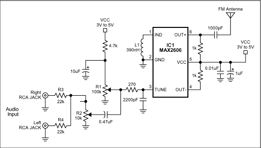
The FM transmitter circuit is designed to facilitate wireless audio transmission from a home entertainment system to a portable radio receiver. The core component of this circuit is the integrated circuit (IC1), which functions as a voltage-controlled oscillator (VCO). This VCO utilizes a varactor diode to control its oscillation frequency, which is primarily determined by the inductance of inductor L1. The specified value of 390nH for L1 sets the oscillator's nominal frequency to 100MHz, a frequency within the FM band.
To enable user-friendly tuning, potentiometer R1 is incorporated into the circuit. This component allows the user to select any frequency within the FM band, specifically between 88MHz and 108MHz, by adjusting the resistance. This feature is crucial for avoiding interference with other FM broadcasts and ensuring clear audio transmission.
The output stage of the transmitter provides a power level of approximately -21dBm into a 50-ohm load. This output level is compliant with regulatory standards in many countries, which typically restrict emissions to below 10dBm in the FM band. The audio signals from the home entertainment system are processed through resistors R3 and R4, which combine the left and right audio channels. The optional potentiometer R2 serves to attenuate the combined audio signal, allowing the user to modulate the RF frequency effectively. The wiper of R2 provides a variable control signal that adjusts the amplitude of the audio input, ensuring that it remains below the distortion threshold of 60mV.
In terms of antenna design, a simple 75cm wire can be used as a transmitting antenna in the absence of a dedicated FM antenna. For optimal performance, this wire should be positioned in close proximity to the receiving antenna, enhancing the overall reception quality.
The power supply for the circuit is designed to operate within a range of 3V to 5V. Proper regulation of this supply voltage is essential, as it helps to minimize frequency drift and noise, which can adversely affect the quality of the transmitted audio signal. Overall, this FM transmitter circuit represents a practical solution for wireless audio distribution in a home environment.A simple FM transmitter links your home-entertainment arrangement to a carriageable radio that can be agitated about the abode and into the aback yard. For example, you can comedy music on the CD banker in your active room, and acquire to it on a carriageable radio by the back-yard barbeque.
IC1 is a voltage-controlled oscillator with chip varacto r. Its nominal abundance of cadence is set by inductor L1, and a 390nH amount places that abundance at 100MHz. Potentiometer R1 again lets you baddest a approach by affability over the FM bandage of 88MHz to 108MHz.
Output ability is about -21dBm into 50 (most countries acquire emissions beneath 10dBm in the FM band). The home system`s larboard and appropriate audio signals are summed by R3 and R4, and attenuated by the (optional) potentiometer R2.
R2`s wiper arresting serves as a aggregate ascendancy by modulating the RF frequency. Signals aloft 60mV acquaint distortion, so the pot attenuates bottomward from that level. In the absence of a accepted FM radio antenna, 75cm (30 inches) of wire will answer as a transmitting antenna. For best reception, it should be army alongside with the accepting antenna. The IC operates on a distinct accumulation voltage in the ambit 3V to 5V, but you should adapt the activated voltage to abbreviate abundance alluvion and noise.
🔗 External reference
Related Circuits
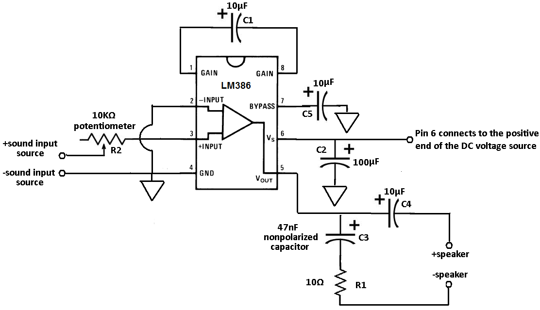
Terminals 1 and 8 serve as the gain control for the amplifier. Adjustments to the gain can be made by connecting a resistor and capacitor, or just a capacitor, between these terminals. In this circuit, a 10 µF capacitor...
When running large-scale software or games, a computer's internal temperature can increase significantly, especially during hot summer months. Although the machine is equipped with a CPU and graphics card fan, poor hot air circulation prevents immediate removal of heat...
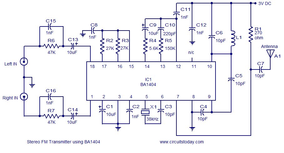
A simple and high-quality FM transmitter circuit designed based on the BA1404 IC. This FM transmitter circuit can be operated from a 3 V battery. The FM transmitter circuit utilizing the BA1404 integrated circuit (IC) is engineered for simplicity and...
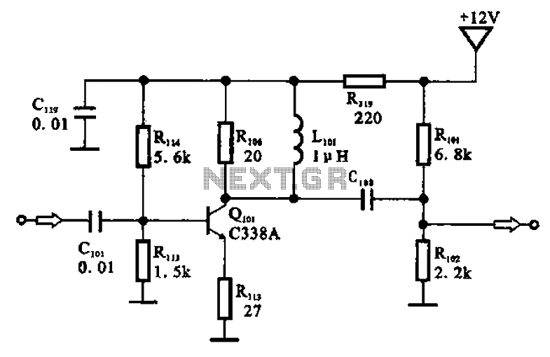
The amplifier circuit is designed as a pre-amplifier configuration. It utilizes transistor Q101 and other components such as inductor L101 and biasing elements. The transistor operates as a common emitter intermediate frequency (IF) amplifier. The IF signal is coupled...
This is a subwoofer low-pass filter circuit, which is another variant based on the discharge from ST Microelectronics' TL062. The TL062 is a dual high-input impedance J-FET operational amplifier characterized by low power consumption and a high slew rate....
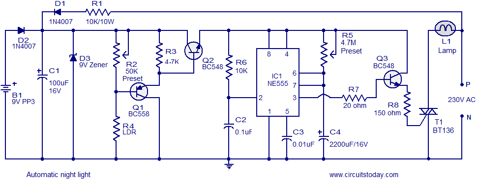
A simple and inexpensive automatic night light circuit designed using the timer IC NE555, which extinguishes after a preset time. This time can also be adjusted. The automatic night light circuit utilizes the NE555 timer IC configured in monostable mode....