
simple intercom circuit with
This two-station intercom circuit utilizes a straightforward design that leverages transistors for amplification and mini speakers for both audio output and input. The circuit operates by having each station equipped with a speaker that captures sound when the "press-to-talk" switch is activated, allowing for two-way communication. The use of 8-ohm mini speakers is advantageous due to their compact size and adequate sound quality for intercom applications.
To enhance the reliability of the circuit, the inclusion of a spring-return switch mechanism is critical. This design choice ensures that the intercom remains in a non-active state when the switch is not pressed, thus preventing accidental activation. Furthermore, powering the speakers from a separate power supply mitigates the risk of instability often associated with high-gain circuits, ensuring clear and uninterrupted audio transmission.
The modular approach of constructing each station in separate enclosures facilitates easy installation and maintenance. The inclusion of power supply ports allows for flexibility in the choice of power sources, accommodating both battery and external power options. Additionally, the connection ports enable straightforward linking of multiple intercom stations, allowing for the expansion of the system as needed.
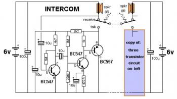
The PCB design process is simplified through the use of dedicated software, which allows for precise layout planning and component placement. The transfer method using a laser printer ensures that the circuit design is accurately replicated onto the PCB, preparing it for the etching process that will create the necessary conductive pathways. This method is efficient and accessible, enabling users to produce a functional intercom circuit with minimal resources. Overall, this intercom design is practical, scalable, and user-friendly, making it suitable for various communication needs.This is a 2-station simple intercom circuit build based on transistors part and using common 8R mini speakers. The speaker works as microphone and generate sound, so there is no need microphone for this intercom.
The "press-to-talk" switches should have a spring-return so the intercom can never be left ON, push on switch can be used for this kind of task. The secret to preventing instability (motor-boating) with a high gain circuit like this is to power the speaker from a separate power supply ! You can connect an extra station (or two extra stations) to this circuit design. Build the circuit into two separated boxes (for 2 stations). On each box should be use 2 ports for external power supply port (if you use external power supply, not battery) and connection port to other stations.
Create some holes for speaker push on switch. Make a PCB in very easy steps. ! Create your PCB design using PCB designer software like Eagle, print out your design on photo paper or glossy paper with laserjet printer. Stick the printed design on the PCB (copper side) and then heat it using hot iron plate. The ink will stick on the PCB and it will be ready for etching process. Note: If you don`t have laserjet printer, then you can print the design on standard paper. Copy the printed design at Copy Service around your location (with glossy paper). 🔗 External reference
Related Circuits
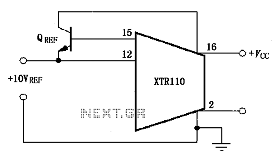
The XTR110 features an internal voltage reference that can output a current of 10mA. By incorporating an external NPN transistor, designated as QREF, the output current capability can be increased. When the VCC voltage reaches 40V, a 2N3055 transistor...
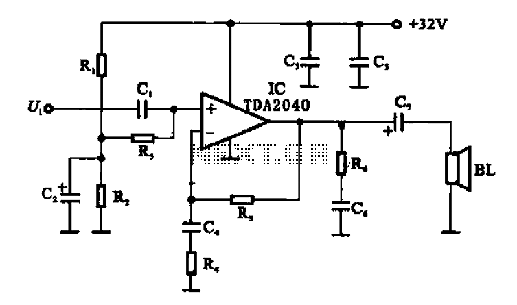
An integrated power amplifier TDA2040 is used in an OTL (Output Transformer-Less) power amplifier circuit, which operates with a +3V single supply as the working voltage. This circuit has a voltage gain of 30 dB (approximately 32 times magnification),...
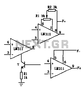
The LM111/211/311 power supply operates within a voltage range of 5V to 15V. It features bias current, offset current, and a differential input voltage range of 30V. The output is compatible with TTL, DTL, and MOS circuits, allowing it...
The provided schematic diagram illustrates an LM741 light/dark sensor circuit, derived from the 741 Op-Amp Tutorial by Tony van Roon. The ECG128/NTE128 transistor can be replaced with any NPN transistor that meets the necessary gain and current specifications for...
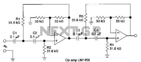
This circuit, which utilizes an LM1458 or a similar operational amplifier, functions as a fourth-order high-pass filter with a roll-off rate of 24 dB per octave. The resistor values Rx/R2 and RJRV can be adjusted to accommodate different cutoff...
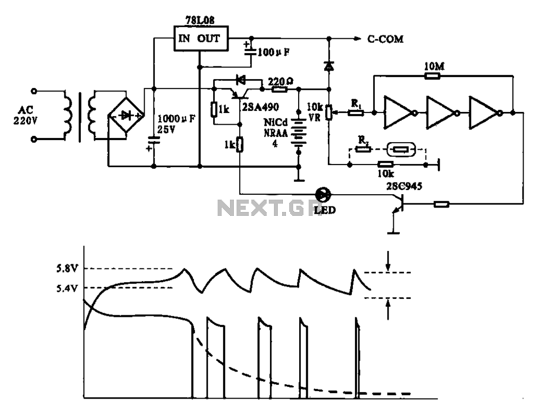
Fast charging circuit that illustrates voltage and current waveforms along with the configuration of the fast charge circuit for the charger. The detection and control circuit consists of three inverters (GMOS) from integrated circuits, enabling automatic control functions. The fast...