
LM111 / 211/311 single voltage comparator circuit diagram
The LM111/211/311 series consists of voltage comparators that are widely used in various electronic applications due to their versatility and performance characteristics. The ability to operate within a voltage range of 5V to 15V makes these devices suitable for battery-powered applications as well as standard power supply systems. The bias current and offset current specifications ensure that the device maintains accuracy in its comparisons, which is critical in precision applications.
The differential input voltage range of 30V allows for the comparison of a wide variety of input signals, making the LM111/211/311 suitable for both low and high-voltage applications. The compatibility with TTL, DTL, and MOS logic levels enables seamless integration into digital circuits, facilitating the design of complex electronic systems.
The capability to drive LEDs and relays expands the functionality of the LM111/211/311, allowing for direct control of visual indicators and electromechanical devices. This feature is particularly useful in automation and control systems where visual feedback or physical actuation is required.
The design flexibility is further enhanced by the option to configure the device as a dual power supply. By using emitter-collector outputs, designers can create circuits that require both positive and negative voltage supplies, accommodating a broader range of applications. The inclusion of external balance adjustment terminals allows for fine-tuning of the circuit, ensuring optimal performance in various conditions.
The gating control terminal provides additional functionality, enabling the user to control the operation of the comparator based on specific conditions or external signals. This feature is particularly valuable in applications where the comparator needs to be selectively activated or deactivated.
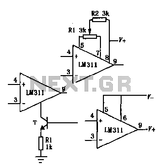
Overall, the LM111/211/311 series comparators are robust components that offer a wide range of functionalities suitable for diverse electronic applications, from simple signal comparisons to more complex control systems. The schematic representation of the basic circuit configuration serves as a useful reference for engineers and designers looking to implement these devices in their projects.Great LM111 / 211/311 power supply voltage range ( 5V ~ l5V), bias current, offset current, the differential input voltage range ( 30V), whose output is compatible with TTL, DTL and MOS circuits, and You can drive LEDs and relays . Single power supply can also be dual power supply with an output emitter-collector outputs and two forms. Such comparator also has external balance adjustment ends and gating control terminal, when used according to select or adjust.
The basic use of the circuit shown in Fig.
Related Circuits
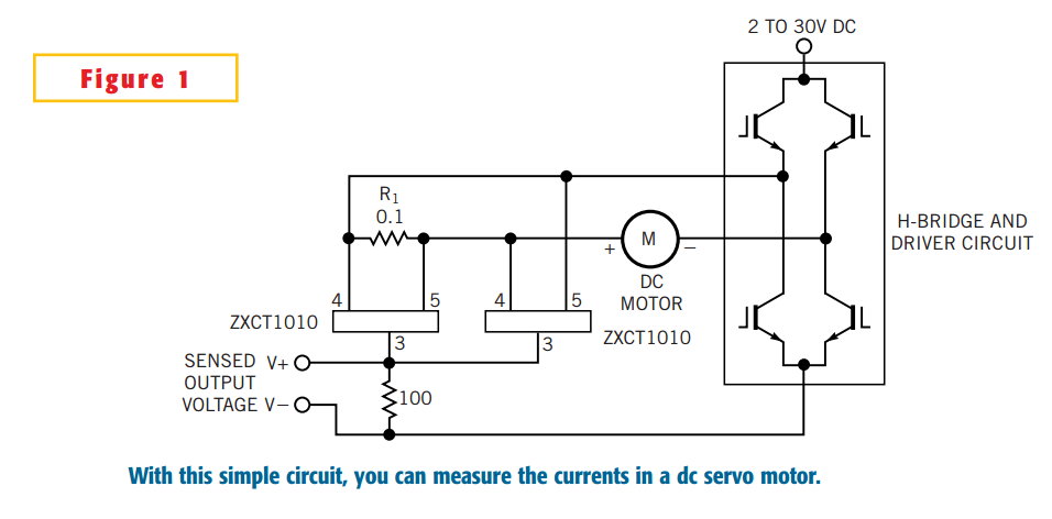
The simple circuit design in Figure 1 lets you measure all components of a current flowing in a dc servo motor. The rectified output of the circuit uses ground as a reference, so you can measure the output by...

The SD1143 transistor offers a gain of approximately 14 dB in this circuit. Its design takes advantage of the fact that a 175-MHz device exhibits significantly higher gain when operated at lower frequencies. The amplifier was initially intended for...
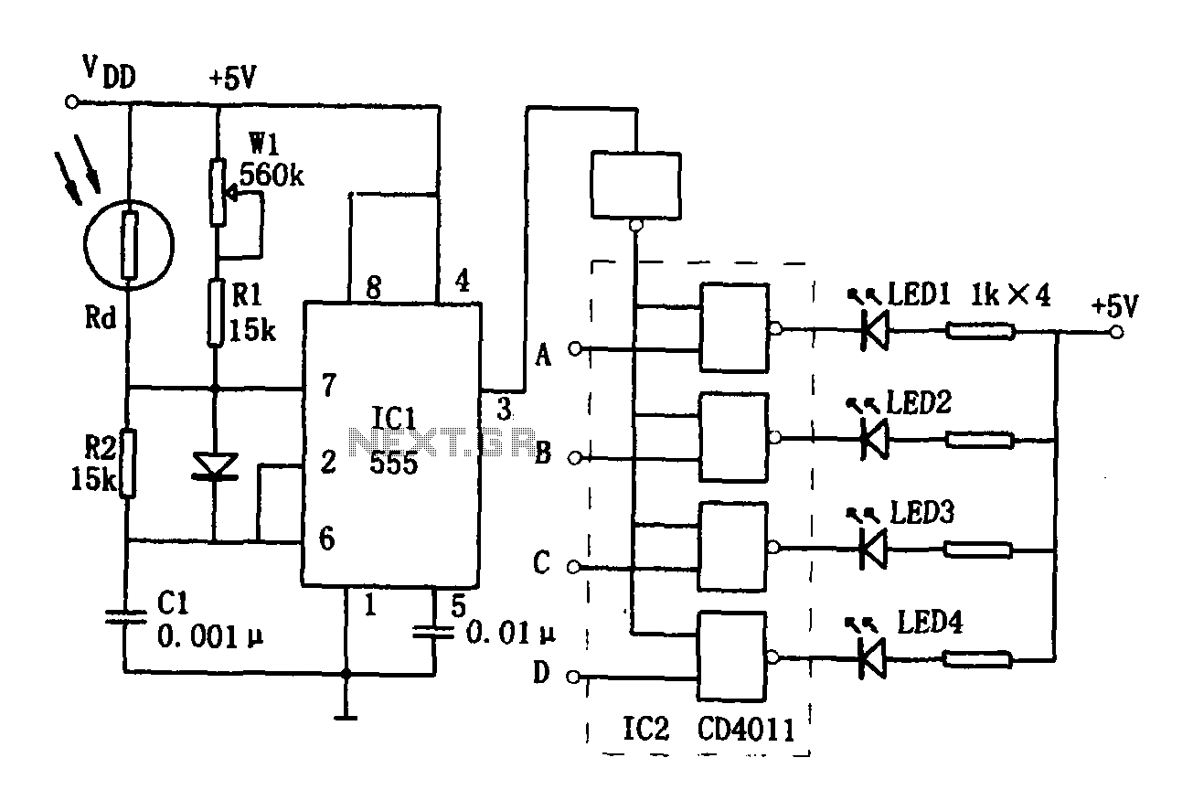
The brightness display circuit consists of a light-sensitive sensor, an oscillation circuit, and an LED display circuit. The light-sensitive sensor is a photosensitive resistor (Rd). The multivibrator is composed of Rd, R1, W1, R2, and C1, along with a...
This bat detector circuit was created by Chris Eve. Initial tests with various salvaged electret microphones demonstrated a good response to frequencies of 50 kHz and higher, with smaller units performing better. Tests indicate that a small electret microphone,...
Most universal radio receivers have a very wide bandwidth that is not particularly suitable for radio amateurs. The better models with narrower bandwidth are almost a... Universal radio receivers are designed to operate over a broad frequency range, making them...
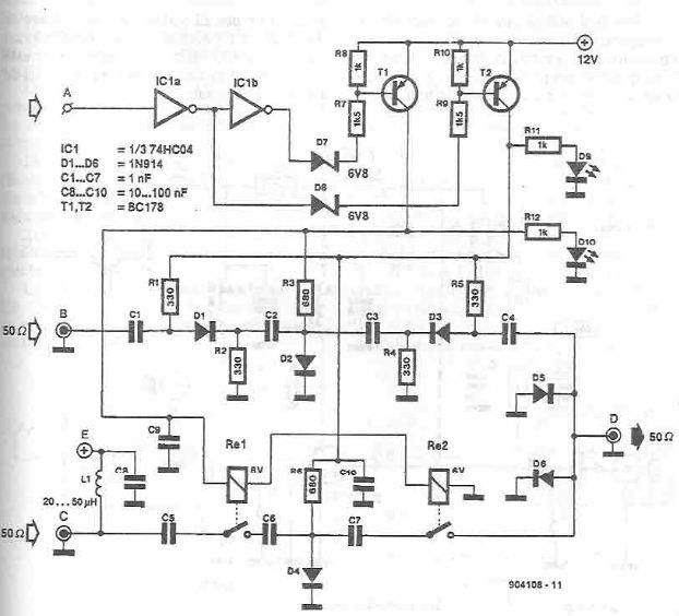
This antenna selector circuit diagram electronic project is constructed using standard electronic components and facilitates the switching between two FM antennas through a logic signal. The gates IC1b and IC1a manage the switching and interface between the required logic...