
simple lead acid battery charger circuit design
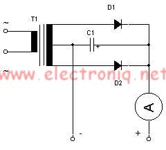
The lead-acid battery charger circuit is designed to efficiently charge lead-acid batteries while ensuring safety and functionality. The center-tapped transformer provides the necessary voltage levels, producing a secondary output of 12V, 0V, and 12V, which allows for full-wave rectification. The two diodes are arranged in a bridge configuration to convert the alternating current (AC) from the transformer into direct current (DC), which is essential for charging the batteries.
The capacitor serves to smooth the output voltage, reducing ripple and providing a more stable charging voltage to the batteries. This is crucial for the longevity and health of lead-acid batteries, as excessive ripple can lead to gassing and damage to the battery cells.
The connection of the charger to the battery terminals must be made with care, ensuring that the positive terminal of the charger connects to the positive terminal of the battery and the negative terminal of the charger connects to the negative terminal of the battery. This correct polarity is vital to prevent damage to both the charger and the battery.
The ammeter is an important component of the circuit, providing real-time feedback on the charging process. When the batteries are in a discharged state, the ammeter will typically show a current draw between 1 and 3 amperes, indicating that the charger is actively supplying power to the batteries. As the batteries approach a fully charged state, the current will decrease, and the ammeter reading will approach zero, signaling that the charging process is complete. At this point, the charger can safely be disconnected from the accumulator, preventing overcharging and potential damage to the battery.
Overall, this simple lead-acid battery charger circuit effectively utilizes basic electronic components to provide a reliable charging solution for lead-acid batteries, ensuring proper operation and maintenance of the batteries throughout their lifecycle.For this simple lead acid battery charger we need a center tapped transformer (12V 0V 12V) which need to give a 5 amperes current, two diodes and one capacitor. To charge the batteries we need to connect the terminal + and - from the charger to the same terminals form accumulator.
When the batteries is empty the ampere-meter connected to the devic e will indicate a value between 1 and 3 amperes, if the batteries are charged the value which is indicated on ampere-meter is almost zero and the charger can be unplugged form accumulator. 🔗 External reference
Related Circuits
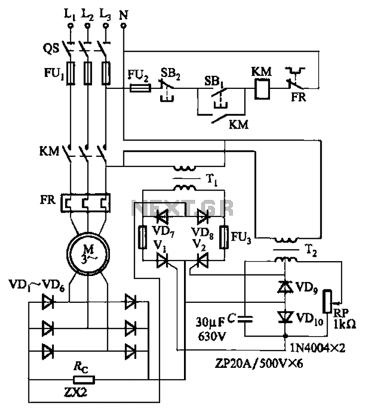
The circuit depicted in Figure 3-171 includes an auxiliary power supply that operates on single-phase AC power. It features a single-phase half-wave controlled bridge composed of diodes VD7, VD8, and thyristors V1, V2. The output current is managed by...
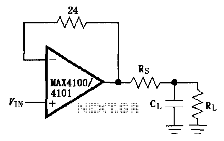
The MAX4100/4101 operational amplifiers utilize a capacitive load drive circuit with an isolation resistor Rs. The MAX4100 and MAX4101 can handle maximum capacitive loads of 5pF and 20pF, respectively, but are susceptible to overshoot and ringing oscillations. To mitigate...
VD represents the voltage drop across the diode, while VTrans indicates the voltage drop across the transistor. The boundary between continuous and discontinuous operation occurs when the output current (io) is zero. A primary consideration in converter design is...
This project is suitable for individuals who enjoy experimenting with electronics. It presents a low risk of damaging the unit. This project involves creating a simple electronic circuit that allows users to engage in hands-on experimentation without significant risk. The...
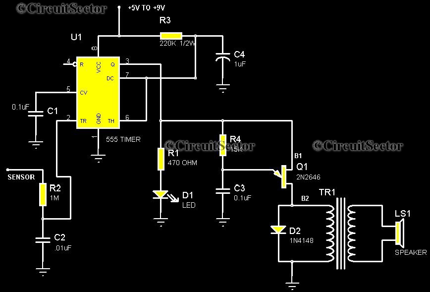
This is a highly sensitive touch plate circuit utilizing the NE555 timer IC, which activates a buzzer when a person touches the metal plate or hovers their hand above it. Compared to previously published touch control switch circuits, this...
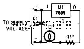
A 7805 can be configured as a constant-current regulator to function as an inrush current limiter. Resistor R1 will maintain a voltage of 5 V across it at all times, resulting in a total current through R1 of 5...