
Auxiliary power supply circuit using variable speed
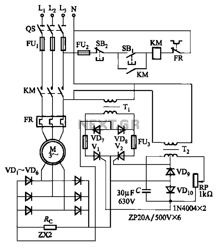
The circuit operates using a single-phase AC power source, which is rectified by the half-wave controlled bridge. The controlled bridge consists of two diodes (VD7 and VD8) and two thyristors (V1 and V2). In this configuration, the diodes conduct during one half of the AC cycle, while the thyristors are triggered to conduct during the other half, allowing for control over the output voltage and current supplied to the load, which in this case is a motor.
The balancing resistor R is essential for ensuring that the output current is evenly distributed between the components of the bridge. This helps maintain stability in the circuit and prevents excessive current from flowing through any single component, thereby enhancing reliability and performance.
The thyristor trigger circuit is designed to provide precise control over the conduction angle of the thyristors. By utilizing a full-wave bridge configuration along with resistive and capacitive phase shifting, the trigger circuit can adjust the timing of the thyristor firing. The adjustment potentiometer RP allows the user to set the desired conduction angle, which directly influences the average output voltage and, consequently, the speed of the motor.
This circuit is particularly useful in applications requiring variable speed control, as it enables the motor to operate smoothly across a broad range of speeds from 300 RPM to 900 RPM. The ability to finely tune the speed through the adjustment of the conduction angle makes this circuit suitable for various industrial and automation applications where precise motor control is necessary. Circuit shown in Figure 3-171. The figure, the auxiliary power supply is single-phase AC power, the single-phase half-wave controlled bridge (diode VD7, VD8 and thyristor vl, V 2 composition) output current supply balancing resistor R. Thyristor trigger circuit is a full -wave bridge resistive and capacitive phase shift. Adjustment potentiometer RP, can change the trigger thyristor conduction angle, thereby enabling the motor can be 300 ~ 900r/min continuously adjustable within range.
Related Circuits
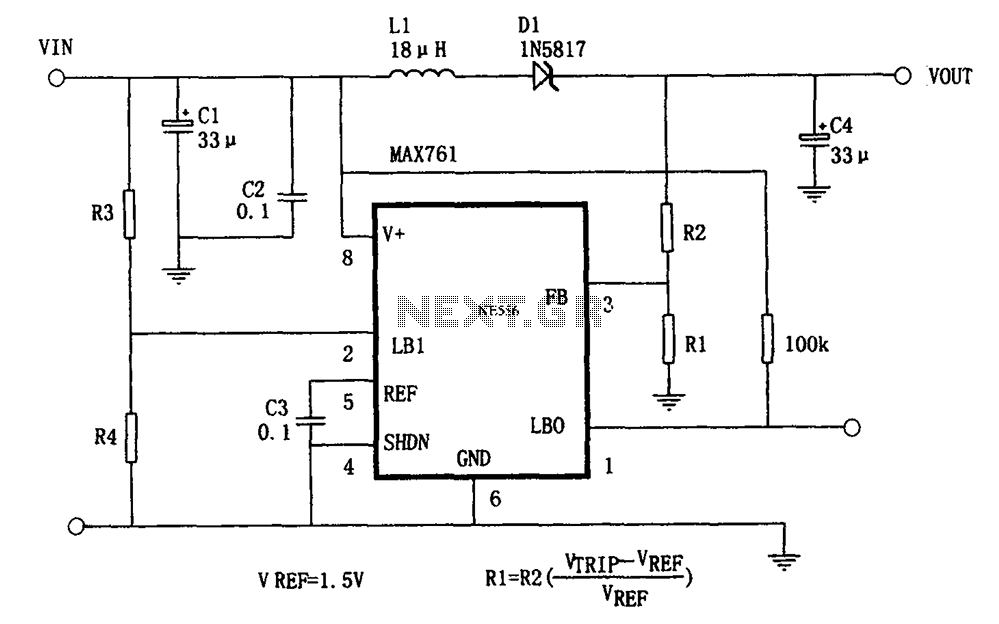
The circuit features an efficient, low-power output voltage boost DC-DC converter, MAX761, along with a few external components that facilitate adjustable power conversion. The output voltage is determined by the ratio of resistors R1 and R2, calculated using the...
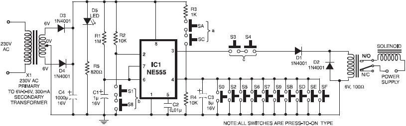
A simple electronic key code lock circuit that requires few external components can be constructed using this schematic diagram. This electronic key code lock circuit is based on a common 555 timer circuit and other standard components. This low-cost...
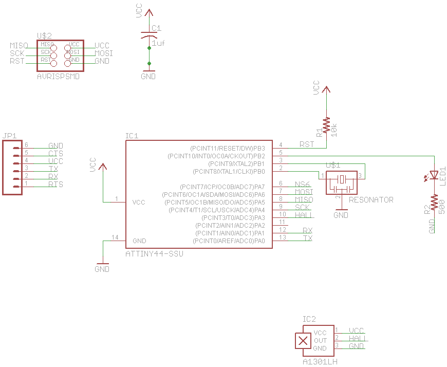
The final project involves cycling rollers that require a method to sense the rotational speed of one of the rollers. Speed sensors on bicycles typically function by detecting a magnet attached to a spoke on one of the wheels...
This is a simple LED circuit that takes power from the USB port. I needed this USB light since long time ago but, finally, I was able to build it. The circuit schematic is so simple: Just one resistor...
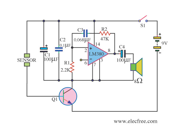
This is a water sensor alarm circuit designed to warn users about water levels. It activates an audible alarm when the sensor comes into contact with water, such as during rainfall. The water sensor alarm circuit functions primarily as a...
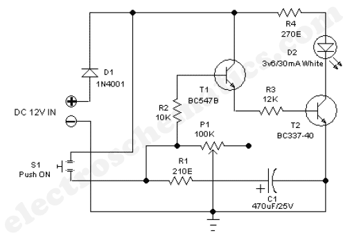
The 555 adjustable timer circuit initiates timing upon activation. A green LED illuminates to indicate that the timing process is underway. Once the designated time period concludes, the... The 555 timer IC is a versatile device widely used in various...