
SIMPLE LED THERMOMETER
The circuit design effectively utilizes the LM34 temperature sensor (IC1) to convert temperature readings into a proportional voltage output. The resistor network involving R1, R2, and R3 not only amplifies the output voltage but also ensures that the system operates within the desired sensitivity range. The inclusion of capacitor C1 is critical for maintaining signal integrity by filtering out noise that could affect temperature readings.
The LM3914 (IC2) is a versatile driver capable of visualizing the output voltage through LED indicators. The choice between dot and bar modes allows users to tailor the display according to their preferences, with dot mode being energy-efficient and bar mode providing immediate visual feedback on temperature changes. The configuration of jumper JU1 plays a pivotal role in toggling between these two modes, making the circuit adaptable to different use cases.
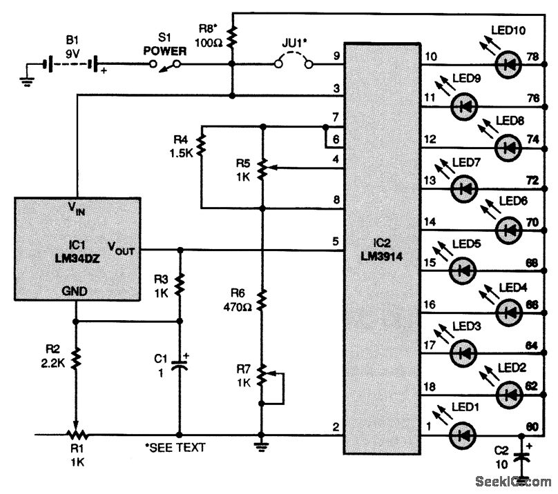
Resistor R8's role in the LED supply circuit is essential for ensuring stable operation, especially when operating in bar mode, where multiple LEDs may be illuminated simultaneously. The adjustment of R8, along with the reference voltages set by R5 and R7, allows for precise calibration of the temperature range displayed, ensuring that the thermometer provides accurate and reliable readings across the specified range. Overall, this circuit exemplifies a well-engineered solution for temperature measurement and visualization, combining efficiency, adaptability, and user-friendly features.As shown, the circuit is powered by a 9-V battery, B1, but it can easily run off any 7- to 10-Vdc power supply. At the heart of the thermometer is IC1, an LM34 temperature sensor. That device produces a voltage between the Vout and GND terminals that is linearly proportional to temperature.
Al-though the output is usually 10 mV/ °F, IC1 is connect ed in a resistor network (made up of R1 to R3) with a gain that provides an output of 40 mV/` °F Capacitor C1 is used as a noise bypass across R1 and R2. Because the voltage output by IC1 will be used by the rest of the circuit to "determine" what the temperature in the room is, potentiometer R1 will have to be calibrated exactly.
The output of IC1 is fed to pin 5 of IC2, an LM3914 LED bar- or dot-graph driver, which is where the actual temperature-determining process occurs. IC2 has 10 internal comparators, the output pins of which are connected to LED1 to LED10. The voltage input to pin 5 is compared by IC2 to the voltages at pins 4 and 6; that process determines which LED or LEDs light.
The LEDs can be set to light either one at a time (dot mode) or progressively (bar mode). When jumper JU1 is not installed, dot mode is enabled. When the jumper is installed, the chip is in bar mode. In dot mode, the LED that corresponds to the correct input voltage lights by itself. When the input voltage increases, an LED representing a higher temperature will light and the LED previously lit will extinguish. In bar mode, the LED representing the temperature will light and all of the lower LEDs will stay lit.
Each mode has its advantages-the dot mode uses less current because only one LED is lit at a time, but the bar mode is easier to read at a glance. Resistor R8 and capacitor C2 provide decoupling for the LED-supply circuit. If bar-mode operation is desired, it is recommended that you reduce the value of R8 to 15 © For a range of 60 to 78 °F to be displayed, pin 6 must have a reference of 3.
345 V and pin 4 should have a reference of 2. 545 V. Those values are obtained through adjustments of potentiometers R5 and R7. 🔗 External reference
Related Circuits
This circuit diagram illustrates a setup for two flashing LEDs designed for various applications, including model construction and recreational uses. It features adjustable flashing speeds controlled by two potentiometers. The circuit comprises a combination of active and passive components....
Savings on electricity bills can be achieved by utilizing alternative power sources. The photovoltaic module, or solar panel, described here can provide a power output of 5 watts. Under full sunlight conditions, the solar panel generates an output voltage...

This circuit uses three easily available 555 timer ICs. All three work as astable multivibrators. The first 555 has an on period and off period equal to 1 sec. This IC controls the on/ off periods of the other...

This project represents an older design that has likely been replaced by a more recent version. Nonetheless, it remains a practical design suitable for a home-brew synthesizer. It is important to note that many of these designs lack circuit...
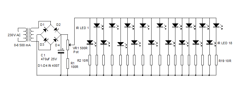
An infrared illuminator emits light in the infrared spectrum and is widely used in night vision cameras to capture images in the dark, particularly in applications such as CCTV cameras. Infrared illuminators are essential components in various surveillance and imaging...
The circuit diagram of an IC Controlled Emergency Light with Charger, also known as a 12V to 220V AC inverter circuit, is presented here. This circuit features automatic activation of the light during mains failure and includes a battery...