
IC Controlled Emergency Light With Charger Circuit
The circuit operates as a robust emergency lighting solution, ensuring that illumination is automatically provided during power outages while safeguarding the battery from overcharging. The NE555 timer, configured in astable mode, generates a consistent pulse width modulation signal, which is essential for driving the MOSFETs effectively. The push-pull configuration of the MOSFETs allows for efficient power conversion, enabling the inverter to produce a stable 220V AC output suitable for driving standard fluorescent lamps.
The inclusion of the overcharge protection circuit is critical for maintaining battery health and longevity. By monitoring the battery voltage and controlling the relay state, the circuit prevents damage that could occur from prolonged overcharging. This feature enhances the reliability of the emergency light system, making it suitable for various applications where dependable lighting is essential during power failures. Furthermore, the design can be modified to accommodate different load requirements or battery specifications, providing flexibility for diverse use cases. Proper thermal management through the use of heat sinks for the MOSFETs ensures that the components operate within safe temperature limits, thereby enhancing the overall performance and lifespan of the circuit.Here is the circuit diagram of IC Controlled Emergancy Light With Charger or simply 12V to 220V AC inverter circuit. The circuit shown here is that of the IC controlled emergency light. Its main features are: automatic switching-on of the light on mains failure and battery charger with over-charge protection.
When mains is absent, relay RL2 is in de-energized state, feeding battery supply to inverter section via its N/C contacts and switch S1. The inverter section comprises IC2 (NE555) which is used in stable mode to produce sharp pulses at the rate of 50 Hz for driving the MOSFETs. The output of IC2 is fed to gate of MOSFET (Q4) directly while it is applied to MOSFET (Q3) gate after inversion by transistor Q2.
Thus the power amplifier built around MOSFETs Q3 and Q4 functions in push-pull mode. The output across secondary of transformer T2 can easily drive a 230-volt, 20-watt fluorescent tube. In case light is not required to be on during mains failure, simply flip switch S1 to off position. Battery overcharge preventer circuit is built around IC1 (LM308). Its non-inverting pin is held at a reference voltage of approximately 6. 9 volts which is obtained using diode D5 (1N4148) and 6. 2-volt zener D6. The inverting pin of IC1 is connected to the positive terminal of battery. Thus when mains supply is present, IC1 comparator output is high, unless battery voltage exceeds 6. 9 volts. So transistor Q1 is normally forward biased, which energises relay RL1. In this state the battery remains on charge via N/O contacts of relay RL1 and current limiting resistor R2. When battery voltage exceeds 6. 9 volts (overcharged condition), IC1 output goes low and relay RL1 gets de-energised, and thus stops further charging of battery.
MOSFETs Q and Q4 may be mounted on suitable heat sinks. 🔗 External reference
Related Circuits
The sensors used are silicon phototransistors and Cadmium Sulfide (CdS) photocells. Both of these sensors allow less current to flow when they are dark than when lighted. Phototransistors change their conductance while photocells change their resistance depending on the...
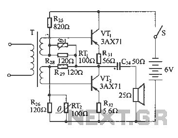
The following diagram illustrates a common output transformerless (OTL) amplifier circuit that delivers an output power of 100 mW. The circuit includes an output transformer and a capacitor, which work in conjunction with speaker units. The frequency characteristics of...
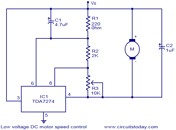
The circuit diagram illustrates a low voltage/low power DC motor speed controller utilizing the TDA 7274 integrated circuit from ST Microelectronics. The TDA 7274 is designed for low voltage and low power applications, featuring an internal voltage reference, a...
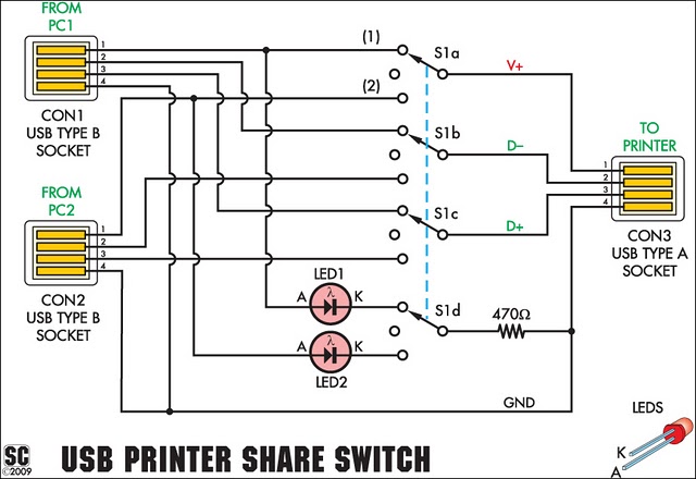
This device enables two computers to share a single USB printer or other USB devices such as an external flash drive, memory card reader, or scanner. A rotary switch is used to select the PC that will connect to...
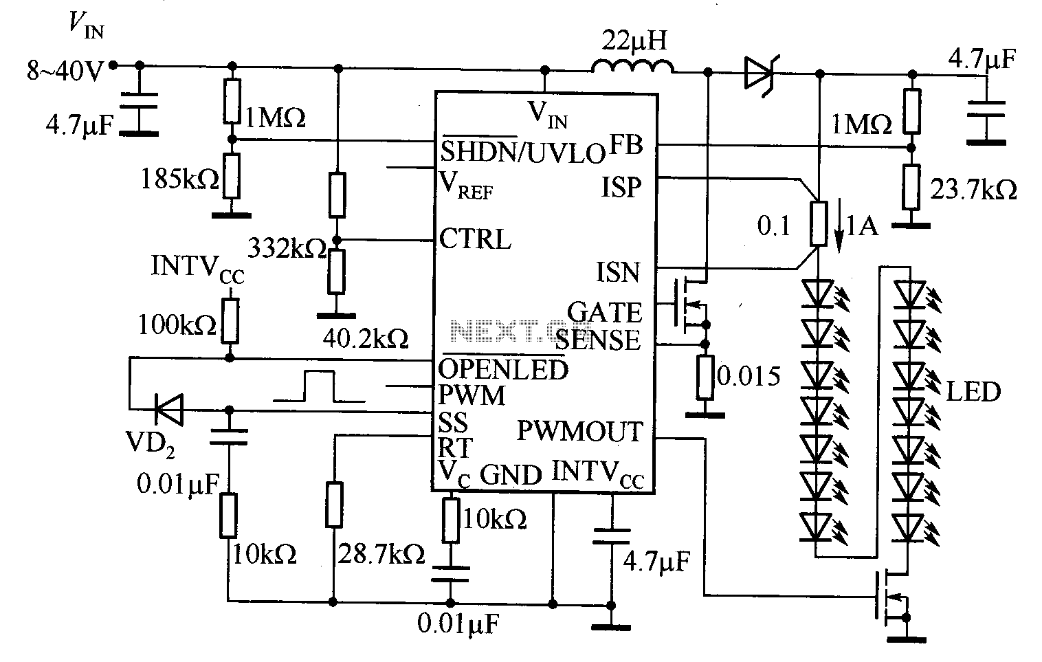
The LT3755 is utilized for high-side current sensing in LED strings, enabling flexible programming and control. It supports a PWM input that allows for a dimming ratio of up to 3000:1, while the CTRL input offers additional analog dimming...
The circuit consists of two building blocks. The first is a square wave oscillator made up of two transistors in a multivibrator arrangement and the second is a CD 4017 decade counter IC. The multivibrator contains two extra components...