
Simple Microphone Preamp
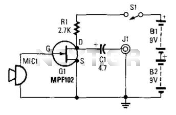
The described preamplifier circuit is designed to amplify low-level audio signals generated by a small dynamic microphone. The microphone serves as the input transducer, converting sound waves into electrical signals. The gate of Q1, which is typically a field-effect transistor (FET), is the primary amplification component in this configuration.
R1, the load resistor, plays a crucial role in setting the operating point of the transistor and determining the gain of the amplifier. The value of R1 can be selected based on the desired output characteristics and the specific microphone being used. The audio signal is extracted from the negative terminal of capacitor C1, which serves to block any DC component from the output, allowing only the AC audio signal to pass through to subsequent stages of processing or amplification.
The output voltage range of 10 to 100 mVpp indicates the circuit's sensitivity to variations in microphone performance, as different microphones will produce varying output levels based on their design and acoustic environment. This preamp circuit is suitable for applications where low-level audio signals need to be amplified for further processing, such as in audio recording systems, public address systems, or any application requiring sound capture and amplification.
Overall, this preamplifier design emphasizes simplicity and efficiency, making it an effective choice for integrating small dynamic microphones into larger audio systems. Proper attention to component selection and circuit layout will enhance performance and reliability in practical applications. This preamp uses a small dynamic microphone coupled to the gate of Ql. R1 is a load resistor. Audio is taken out b etween the negative side of CI and ground. Output will be between 10 and 100 mVpp, depending on the microphone. 🔗 External reference
Related Circuits
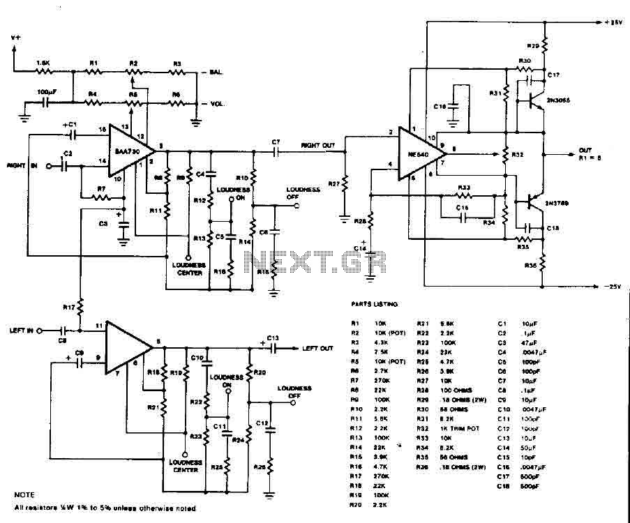
This circuit is an audio preamplifier that has balance, tone, and loudness controls. It should be suitable as an example of good design for audio applications. The audio preamplifier circuit utilizes the BAA730 and NE540 integrated circuits, which are...

Metronome is an electronic device that keeps rhythm by making regulated clicking sounds, device used to keep the beat while playing a musical instrument. The circuit is an old design to build, but you will find it useful. The metronome...
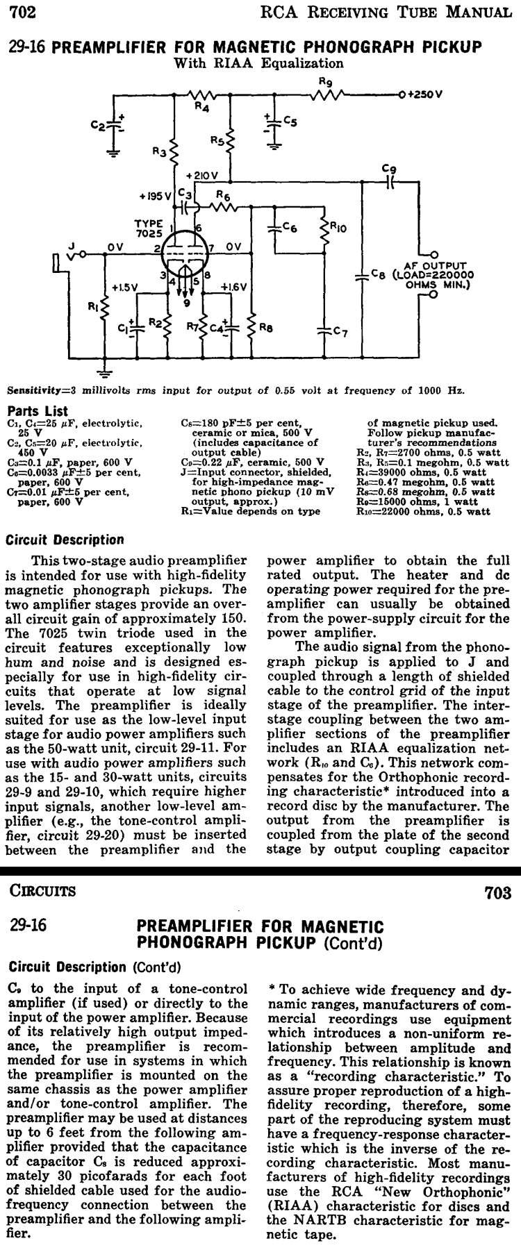
This two-stage audio preamplifier is designed for high-fidelity magnetic phonograph pickups, providing an overall gain of approximately 150. The circuit is sourced from the RCA tube receiving manual and is intended for use with the renowned RCA 7025 twin...
This circuit utilizes the widely available LM3914 integrated circuit (IC). The IC is straightforward to operate, does not require external voltage regulators due to its built-in voltage regulation feature, and can be powered from nearly any voltage source. The LM3914...
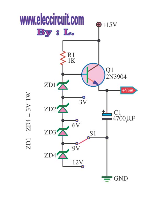
This is a DC regulator circuit that can provide multiple output voltages simply. It functions as a simple step-down DC converter and is designed with a fixed resistor R1. The described circuit operates as a DC voltage regulator, specifically designed...

This design circuit is for a stereo amplifier intended for a high-sensitivity stereo parabolic microphone, enabling the listening of distant sounds. Unlike typical parabolic microphones that are monophonic, this unit features a stereo audio path, resulting in more realistic...
Warning: include(partials/cookie-banner.php): Failed to open stream: Permission denied in /var/www/html/nextgr/view-circuit.php on line 713
Warning: include(): Failed opening 'partials/cookie-banner.php' for inclusion (include_path='.:/usr/share/php') in /var/www/html/nextgr/view-circuit.php on line 713