
big e stereo parabolic microphone

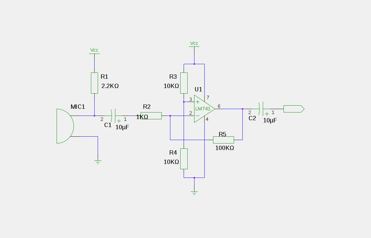
The stereo amplifier circuit is designed to optimize the performance of a high-sensitivity stereo parabolic microphone, which is particularly useful in applications requiring the capture of distant sounds. The mini condenser microphone acts as the primary transducer, converting acoustic energy into an electrical signal. The biasing provided by resistor R1 is critical for the operation of the internal amplifier transistor, ensuring that the microphone operates within its optimal range.
The use of the 2N3906 PNP transistor as a low-noise input amplifier is significant, as it minimizes the noise introduced at the initial stage of amplification. This is crucial for maintaining the fidelity of distant sounds. The adjustable gain feature, provided by the 10K potentiometer, allows for fine-tuning of the audio signal level, accommodating various listening environments and user preferences.
The 1458 op-amp is configured in an inverting manner to achieve a fixed gain of 10X, which is suitable for driving low-impedance loads such as headphones. The output stage is designed to deliver sufficient power while maintaining audio quality. Capacitor C9 serves to decouple the DC component from the audio signal, ensuring that only the AC audio waveform is passed to the headphones or recording device.
Impedance protection through resistor R13 is essential for preventing potential damage to the op-amp and ensuring that the audio signal remains undistorted. The voltage divider formed by resistors R16 and R17 is a critical component for setting the DC bias, ensuring that the op-amp operates efficiently within its linear range.
Power supply stability is enhanced by capacitors C13 and C14, which filter out any noise from the power source, thereby improving overall circuit performance. Additionally, the filtering of the DC for the preamp transistors through R15 and C11 further ensures that the input stage operates without interference from power supply variations.
Finally, the inclusion of diode D1 and resistor R18 provides a safeguard against reverse polarity, protecting the circuit from potential damage due to incorrect battery connections. This comprehensive design approach ensures that the stereo amplifier circuit delivers high-quality audio performance for applications involving high-sensitivity parabolic microphones.This is a design circuit for a stereo amplifier for a high sensitivity stereo parabolic microphone. This circuit can be used for listening to distant sounds. Typical parabolic microphones are mono phonic, this unit has a stereo audio path that helps produce more realistic sounding audio. This is the figure of the circuit. The mini condenser microp hone converts sounds into an electrical signal. Resistor R1 provides bias for the condensor microphone`s internal amplifier transistor. The 2N3906 PNP transistor acts as a low noise microphone input amplifier. The 10K gain potentiometer is used for adjusting the audio signal level. A stereo 10K audio taper potentiometer can be used for adjusting both channels simultaneously, or individual 10K trimmers can be used for fixed gain applications. The preamp output signal is fed into the 1458 op-amp, which boosts the audio to a level that is sufficient for driving an 8-ohm headphone or a tape recorder input.
The 1458 amplifier stage is fixed gain (10X) in the inverting configuration, it drives the headphone speakers. Capacitor C9 provides DC isolation from the 1458 op-amp output, which sits at half of the supply voltage.
Resistor R13 provides impedance protection for the op-amp output and reduces audio distortion when driving low impedance headphones. DC bias for the 1458 op-amps is set at half of the supply voltage by the R16/R17 voltage divider. Capacitors C13 and C14 filter the DC power supply for the op-amp stage. The DC is further filtered for the input preamp transistors through resistor R15 and capacitor C11. Diode D1 and resistor R18 protect the circuit from reverse battery polarity. 🔗 External reference
Related Circuits
An electret microphone has been connected to an operational amplifier (op-amp), with the output directed to an Arduino microcontroller. The analog-to-digital converter (ADC) on the microcontroller converts a voltage range of 0 to 5 volts into a 10-bit number,...
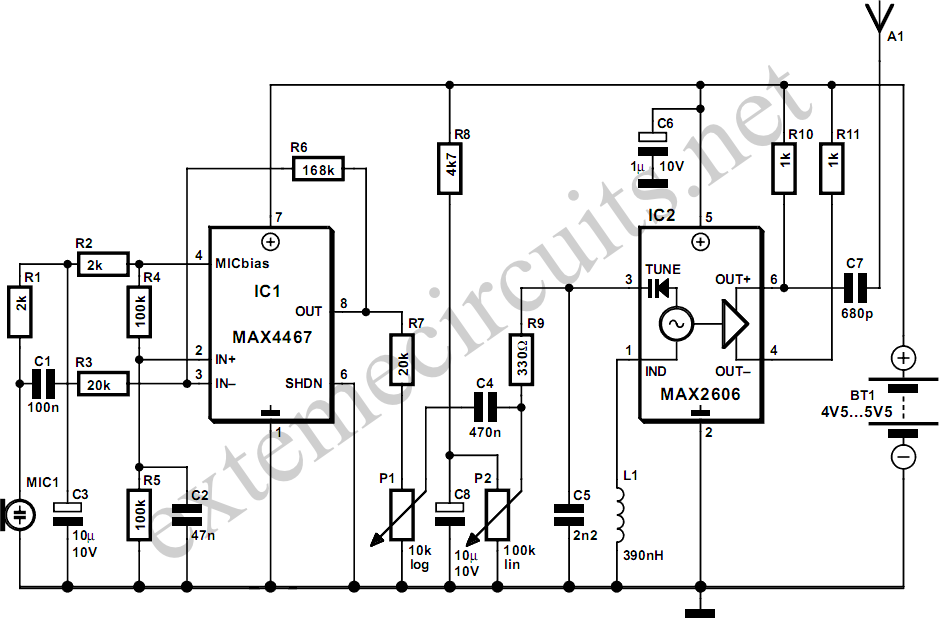
This project involves a simple and cost-effective transmitter designed for hobbyists and home experimenters, capable of transmitting speech over a short distance. It functions as a cordless microphone, utilizing two integrated circuits from Maxim. The first IC, MAX4467, acts...
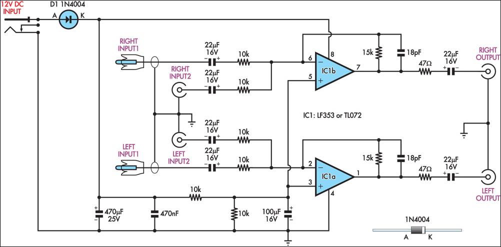
This circuit combines two separate line-level stereo (left and right) signals into a single stereo output, eliminating the need to switch between two sets of input signals. In this application, it is utilized to connect stereo audio from a...
This circuit is primarily designed to provide a microphone input for standard home stereo amplifiers. Utilizing a battery supply minimizes the risk of low-frequency hum interference from mains power, simplifying the connection to the amplifier by eliminating the need...
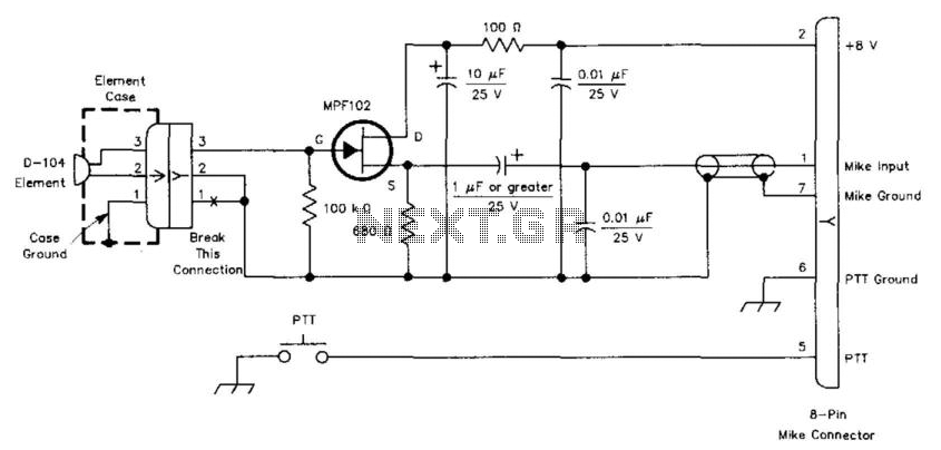
This circuit is designed to interface a high-impedance microphone with a radio transceiver that requires a low-impedance microphone. The power supply can be provided either by a battery or sourced from the transceiver itself. This circuit typically employs a preamplifier...
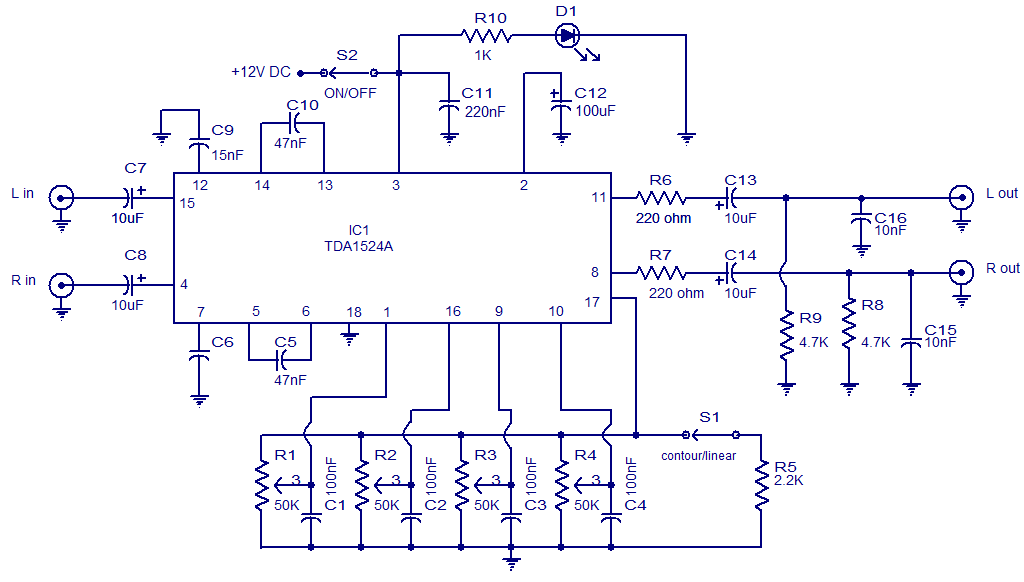
The following circuit illustrates the TDA1524 IC Stereo Preamplifier Circuit Diagram. Features include the ability to control volume, balance, and bass. The TDA1524 is a highly integrated stereo preamplifier IC designed for audio applications. This circuit configuration allows for the...