
Simple Motorcycle AlarmCircuit by Ron J
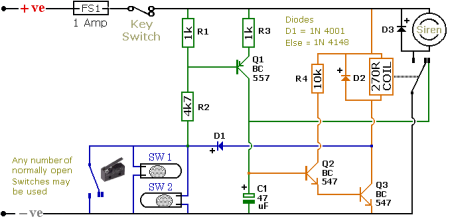
The Simple Motorcycle Alarm Circuit Diagram is designed to enhance the security of motorcycles by utilizing a series of micro-switches strategically placed on removable panels. These micro-switches serve as sensors that detect unauthorized access to critical components, such as the seat or fuel tank, which are often targeted by thieves.
The circuit typically consists of a power supply, often a 9V battery, that powers the entire alarm system. The micro-switches are connected to a central control unit, which monitors their status. When a removable panel is disturbed, the corresponding micro-switch is activated, sending a signal to the control unit. This activation triggers an alarm, which can be an audible sound or a flashing LED light, alerting the owner and deterring potential thieves.
In addition to the micro-switches, the circuit may include a reset button that allows the user to deactivate the alarm after confirming that the panels are secure. It may also feature a delay timer to prevent false alarms caused by minor disturbances, such as vibrations from passing vehicles.
The schematic can be further enhanced by integrating a remote control system, allowing the user to arm or disarm the alarm from a distance. This feature adds convenience and additional layers of security, as it enables the owner to monitor the motorcycle without needing to approach it directly.
Overall, the Simple Motorcycle Alarm Circuit Diagram provides a practical solution for motorcycle security, utilizing basic electronic components to create an effective alarm system that can be easily implemented.The following schematic shows the Simple Motorcycle Alarm Circuit Diagram designed and drawn by Ron J. It uses micro-switches to protect removable panels and.. 🔗 External reference
Related Circuits

The cut on a fader is fundamentally different from a transform. It is not an instantaneous on/off switch; rather, it features a gradual slope that can range anywhere from a few hundred microseconds to tens of milliseconds. This duration...
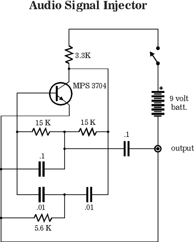
This is a signal injector designed for individuals who may not have access to extensive test equipment. It can be utilized for tracing audio circuits during troubleshooting or for testing audio circuits that require an input signal. The injector...
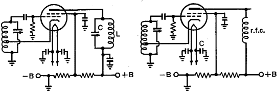
One of the significant challenges in designing vacuum-tube oscillators is maintaining a constant frequency despite mechanical vibrations, temperature fluctuations, voltage variations in the supply lines, and changes in the load power drawn from the circuit. The effects of variable...
A humidity sensor can be utilized to provide an alert for boat leakage or to notify when books are at risk of being damaged due to heavy rain affecting a compromised roof. Humidity sensors are essential devices that measure the...

The power windows operate slowly, but connecting 12 volts directly to the motors allows them to function properly. A previous discussion mentioned using a common 5-pin ice cube relay, but there was no confirmation of its effectiveness. The power...

A simple low-power AM/FM radio receiver electronic project can be designed using the TA8122 integrated AM/FM receiver, manufactured by Toshiba Semiconductor. This radio receiver circuit is suitable for portable radio applications and similar devices. The TA8122 radio receiver circuit...
Warning: include(partials/cookie-banner.php): Failed to open stream: Permission denied in /var/www/html/nextgr/view-circuit.php on line 713
Warning: include(): Failed opening 'partials/cookie-banner.php' for inclusion (include_path='.:/usr/share/php') in /var/www/html/nextgr/view-circuit.php on line 713