
Simple Schematic for VCA mixer
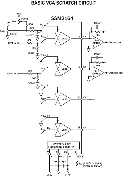
The operation of a fader, particularly in the context of audio mixing and scratch techniques, is critical for achieving smooth transitions and dynamic sound manipulation. The gradual slope of the fader cut allows for nuanced control over audio signals, which is essential for DJs and sound engineers. The relationship between the fader's movement speed and the audio output quality is a significant aspect of circuit design. A well-calibrated fader circuit minimizes popping sounds, which can detract from the listening experience.
In terms of circuit design, achieving a balance between fast response times and audio fidelity is paramount. The use of components such as voltage-controlled amplifiers (VCAs) can help in creating a responsive circuit that minimizes artifacts like popping. However, the choice of components and their arrangement on the PCB is crucial. High-quality capacitors, resistors, and operational amplifiers should be selected to ensure that the signal path remains clean and free of unwanted noise.
Moreover, the implementation of digital signal processing (DSP) techniques can enhance the performance of such circuits. By incorporating DSP, it is possible to refine the audio output further, allowing for dynamic adjustments that can adapt to the user's mixing style. This approach, while more complex, can yield superior results compared to traditional analog methods.
In conclusion, while DIY enthusiasts may face challenges in creating a high-performance VCA fader circuit without popping, understanding the intricacies of circuit design, component selection, and potential use of DSP can lead to more successful outcomes. The insights gained from professional-grade products can serve as valuable lessons for hobbyists aiming to improve their designs.How a cutt of a fader is differnet form a transform What does skratch tricks have to do with the fader function The cut on a fader is completely different from a transform. It isn`t an instant on/off but a sloped cut in perhaps anywhere from a few hundred microseconds to tens of milliseconds depending on several factors such as how fast you move the fader, how sharp
the slope is set, and the quality and wear of the crossfader. If you do a direct transform-like cut-in you will have an unnatural and unpleasant popping sound. I haven`t tested the circuit but would say that there`s a tradeoff between reaction speed and smoothness. The slower the reaction speed the more the pop gets smoothed out. Really slow speeds can make even the crappiest faders sound like mint faders but then of course then the VCA becomes unresponsive, making it unusable for scratch mixing.
BTW, the AEM-100/AEM-100i uses a more complex control circuit which I`ve intentionally avoided for the purposes of keeping this discussion on the level of what any hobbyist can build. I had a fader hooked up with a normally open magnetic reed relay, fed with a +5v, which could switch way faster than you could ever need, only it made an audiable pop everytime it switched.
Actually that was the main reason I posted the simpler schematic. It`s insane to use relays on an audio signal circuit because they`ll generate all sorts of crazy electromagnetic signals which you`ll hear in the output. To do a full finished and refined manufactured product requires skilled PC board layout, metal manufacturing, circuit design, and sometimes "firmware" (basically writing a software program to do mixer controls).
That`s not to mention capital, sales, marketing, etc. etc. I`ve already suggested all I can for the DIY hobbyists. It`s better at this point if Audio Innovate makes things happen for real by making good reliable DJ products that you guys want because this is our expertise. To do a full finished and refined manufactured product requires skilled PC board layout, metal manufacturing, circuit design, and sometimes "firmware" (basically writing a software program to do mixer controls).
That`s not to mention capital, sales, marketing, etc. etc. I`ve already suggested all I can for the DIY hobbyists. It`s better at this point if Audio Innovate makes things happen for real by making good reliable DJ products that you guys want because this is our expertise. So baysically what you are saying is that its impossible for a DIY electronics hobbyist to assemble a VCA 50k fader `skratch` circuit that will respond quick enough with no popping Because I was under the impression that it was done, then I was under the impression that it had popping, and I thought we were adressing that issue, and now it seems like you are telling me its not possible and you have done what you could If thats the case U already had it hooked up with a magnetic reed relay which is capable of switching 300+ times per second, and it worked fine, just had horrendus popping.
but youre telling me all this work we have done is going to have the same outcome So baysically what you are saying is that its impossible for a DIY electronics hobbyist to assemble a VCA 50k fader `skratch` circuit that will respond quick enough with no popping Because I was under the impression that it was done, then I was under the impression that it had popping, and I thought we were adressing that issue, and now it seems like you are telling me its not possible and you have done what you could If thats the case U already had it hooked up with a magnetic reed relay which is capable of switching 300+ times per second, and it worked fine, just had horrendus popping. but youre telling me all this work we have done is going to have the same outcome Hopefully you can also respect that as many manufacturers will view this forum it`s not appropriate
🔗 External reference
Related Circuits
The described shunt-feedback configuration facilitates the straightforward incorporation of frequency-dependent networks, enabling a practical and unobtrusive switchable tilt control as an optional feature. When switch SW1 is in the first position, a gentle shelving bass boost and treble cut...
This network wiring tester consists of two components: a transmitter unit, which is powered and installed at the network's starting point, and a passive receiver unit that can be moved from socket to socket. Both units contain eight LEDs,...
This website was developed to assist students in discovering ideas for their projects or final year projects (FYP). All content presented here is sourced from reliable blogs, websites, and forums. The owner of this website assumes no responsibility for...
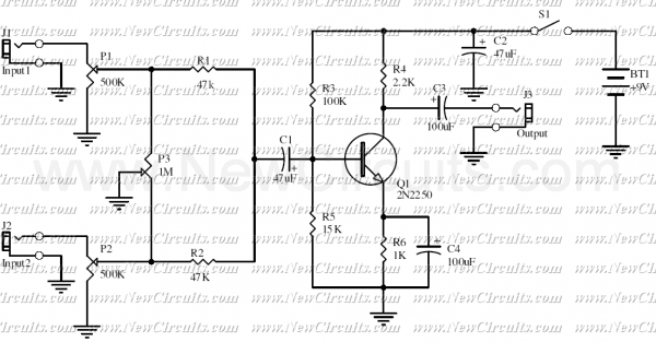
This is a classic signal mixer that is used for audio purpose. VR1 & VR2 are inputs audio volume controllers and VR3 is used to control the balance between Input1 and Input2. Connect a dynamic microphone to Input1 and...
A video switcher circuit is required to display multiple sources on a single monitor. The circuit schematic below features the MAX454, which serves as the core component of this video switcher. The MAX454 is a video multiplexer-amplifier manufactured by...

The fundamental digital circuits include Flip-Flops and Counters, both of which are present in this design. This circuit can be cascaded to create a six-digit event counter, and a simple frequency counter can also be constructed. Modern implementations are...
Warning: include(partials/cookie-banner.php): Failed to open stream: Permission denied in /var/www/html/nextgr/view-circuit.php on line 713
Warning: include(): Failed opening 'partials/cookie-banner.php' for inclusion (include_path='.:/usr/share/php') in /var/www/html/nextgr/view-circuit.php on line 713