
Simple Ni-Cd Battery Charger

The Ni-Cd battery charger circuit employs the LM317 voltage regulator, which is a versatile and widely used component in power supply applications. The LM317 is capable of providing a stable output voltage and can be configured to deliver a specific current for charging purposes. In this design, the charging current is controlled by a variable resistor (R1), allowing for flexibility in charging different capacities of Ni-Cd batteries.
The circuit typically consists of the LM317 IC, a few passive components including R1, and additional resistors and capacitors to stabilize the output and improve performance. The input voltage must be higher than the desired output voltage, which is typically set to around 1.2 V for Ni-Cd batteries. The current flowing through the battery can be adjusted by changing the resistance value of R1, thus allowing the circuit to accommodate various battery sizes and charging requirements.
For optimal performance, it is recommended to include a heat sink for the LM317, as it can generate heat during operation, especially when charging at higher currents. A diode may also be placed in parallel with the battery to prevent reverse current flow when the charger is disconnected.
In summary, this Ni-Cd battery charger circuit is an efficient and adaptable solution for charging Ni-Cd batteries, leveraging the capabilities of the LM317 voltage regulator to provide a controlled charging current through simple component adjustments.This Ni-Cd battery charger is a circuit based on the regulator IC lm317.This circuit is very simple and uses minimum components. By varying value of resistor R1 from 1 ohm to 120 ohms, charging current can be varied from mA to 1.25 A.
Th.. 🔗 External reference
Related Circuits
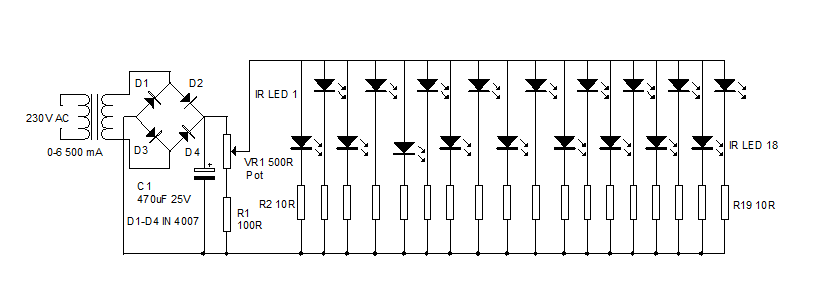
An infrared illuminator emits light in the infrared spectrum and is widely used in night vision cameras to capture images in the dark, particularly in applications such as CCTV cameras. Infrared illuminators are essential components in various surveillance and imaging...
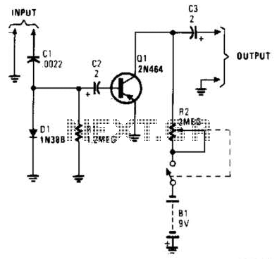
In this circuit, C1, D1, and R1 form an envelope detector. C2 couples audio to the base of Q1. R2 can be adjusted for the desired gain. The circuit under discussion utilizes an envelope detector, which is a fundamental component...
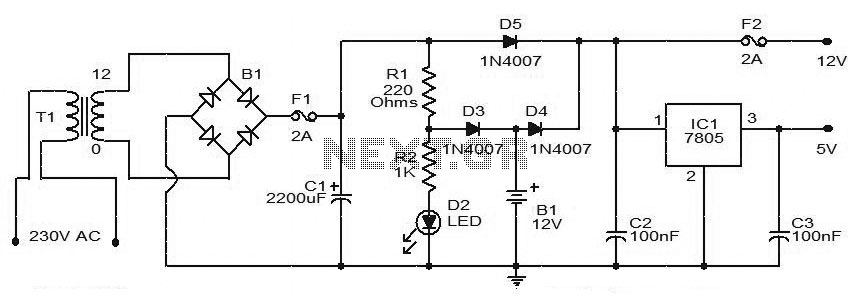
This circuit diagram represents a simple Uninterruptible Power Supply (UPS) capable of delivering 12V unregulated and 5V regulated DC output. The transformer T1 reduces the mains voltage to 12V AC, which is then rectified by bridge B1. The rectified...
A low-cost DC adapter can be utilized to construct a stabilized and uninterruptible 9V power supply. For safety and cost-effectiveness, a simple unstabilized 12V DC adapter serves as the power source; a universal adapter set to 12V will also...
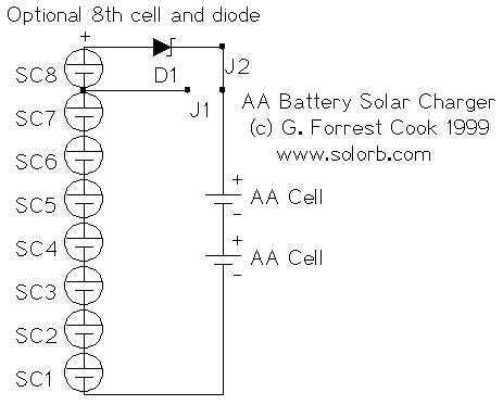
This almost trivial circuit may be used to charge a pair of AA or AAA sized rechargeable battery cells from sunlight. The circuit has been used to keep a Palm Pilot and walkman radio running perpetually. This is an...
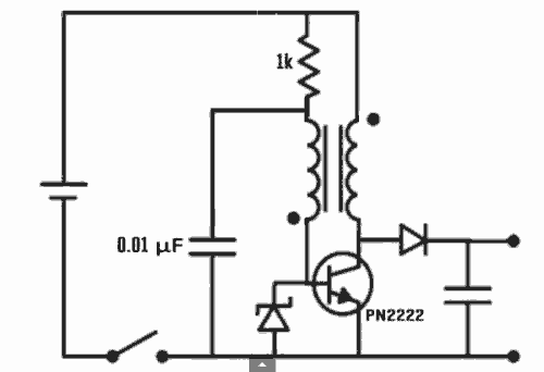
Excellent Joule thief circuit idea! The Joule Thief is a simple yet effective circuit designed to extract usable voltage from low-voltage power sources, such as depleted batteries. This circuit operates on the principle of boosting voltage through the use...