
Simple Signal Tracer Circuit
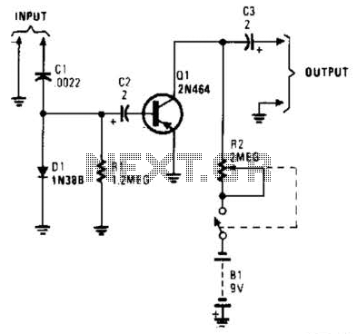
The circuit under discussion utilizes an envelope detector, which is a fundamental component in demodulating amplitude-modulated (AM) signals. The envelope detector consists of a capacitor (C1), a diode (D1), and a resistor (R1). The primary function of this trio is to extract the envelope of the incoming modulated signal, effectively allowing the audio signal to be recovered from the carrier wave.
C1 serves to smooth the rectified output from D1, which is crucial for ensuring that the audio signal is clean and free from high-frequency noise. The value of C1 is selected based on the frequency of the input signal and the desired response time of the envelope detector. D1 is typically a silicon diode, chosen for its low forward voltage drop and fast switching characteristics, which are essential for accurately tracking the envelope of the incoming signal. R1 acts as a load resistor that determines the time constant of the circuit in conjunction with C1, influencing how quickly the circuit responds to changes in the input signal.
C2 is employed to couple the audio signal to the base of transistor Q1. This coupling capacitor ensures that the DC biasing of the transistor is not affected by the audio signal while allowing the AC audio component to pass through. The choice of C2's value is critical as it must be low enough to allow the full audio frequency range to be transmitted without attenuation.
R2 is an adjustable resistor that provides a means to control the gain of the circuit. By varying the resistance, the amount of feedback to Q1 can be altered, thus adjusting the amplification of the audio signal. This adjustability is vital for tailoring the circuit's performance to match the specific requirements of the application, whether it be for a low-sensitivity signal or a more robust amplification need.
Overall, this circuit configuration is widely utilized in various audio processing applications, including radio receivers and signal processing devices, where accurate audio extraction from modulated signals is required. Proper selection of component values and configurations is essential for optimal performance. In this circuit, C1/D1/R1 form an envelope detector. C2 couples audio to the base of Ql. R2 can be adjusted for the desired gain. 🔗 External reference
Related Circuits
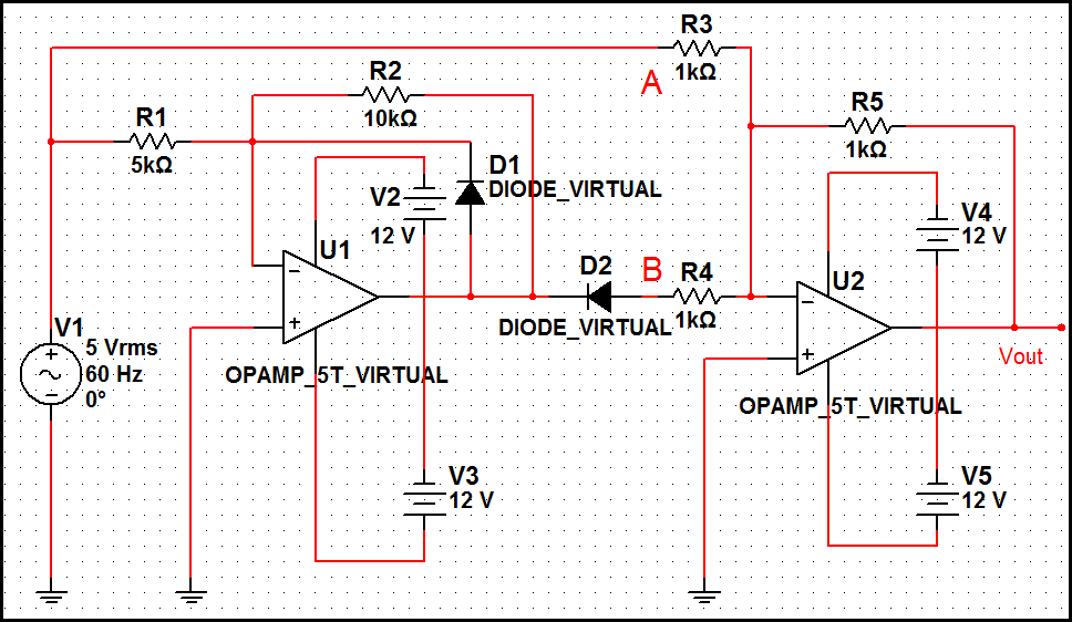
The optimal operational amplifier circuit used to convert a sine waveform into a rectangular waveform is the Schmitt trigger circuit. The Schmitt trigger circuit is a vital component in signal processing, particularly for converting analog signals into digital signals. It...
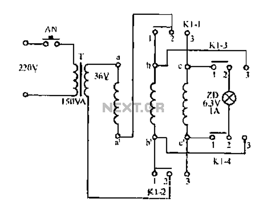
Figure aa, bb, and ce represent three-phase windings. A double throw switch Kl-1 to Kl-4 is positioned on the left side, connecting phases 1 and 2. At this point, aa and bb are in series with the secondary of...
The MiniLOGGER provides 8-channel analog input (-99mV to +999mV), 1-channel pulse input, battery backup 256kB SRAM, Real-time Clock, and RS232C. Start/Stop recording can be made by MANUAL switch or preprogrammed Start/Stop Time. The format of uploading data is ASCII...
The simplest polarity protection technique is to connect a series diode to the power line input. The diode conducts only when the power supply is connected correctly. A series diode is an effective method for preventing reverse polarity in electronic...
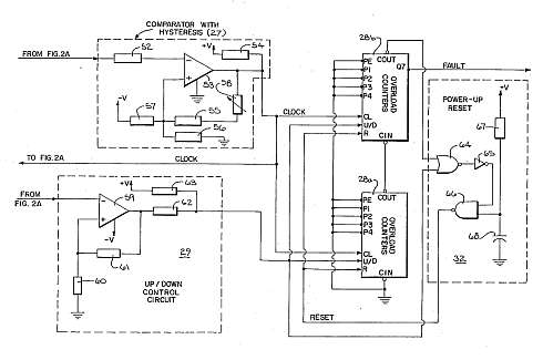
This motor overload circuit allows for short-term overdriving of a system, which is dependent on heat buildup. An overload detection circuit safeguards the motor against currents exceeding the rated current for specific exposure durations. The permissible exposure times are...
The MSF transmitter transmits time data bit-by-bit over 60 seconds each minute by modulating a 60 kHz carrier frequency. It employs a continuous wave (CW) signal. Two bits are sent every second through variations in the duration and number...
Warning: include(partials/cookie-banner.php): Failed to open stream: Permission denied in /var/www/html/nextgr/view-circuit.php on line 713
Warning: include(): Failed opening 'partials/cookie-banner.php' for inclusion (include_path='.:/usr/share/php') in /var/www/html/nextgr/view-circuit.php on line 713