
simple optical switch
The circuit utilizes a phototransistor sensitive to infrared light, which acts as a light sensor. When IR light falls on the phototransistor, it allows current to flow through, creating a voltage drop across the connected resistor. This voltage drop is crucial for the operation of the 555 timer, which is configured in a monostable or astable mode depending on the application. The choice of the resistor value is critical as it sets the sensitivity of the light detection. The relationship between the voltage drop, collector current, and resistance is fundamental for calibrating the circuit to respond to varying light levels.
In applications requiring precise light detection, a variable resistor (trimmer) can be included in the circuit to allow for fine adjustments to the threshold voltage. This enables the circuit to be tuned for specific light levels, enhancing its performance in different lighting conditions.
The 555 timer's output can be used to drive various loads, which can include relays for switching larger currents or controlling other electronic components. The versatility of the 555 timer allows it to be used in many applications, from simple timers to more complex control systems.
For scenarios where an inverted output is needed, the incorporation of a bipolar transistor in an inverting configuration is a practical solution. This arrangement allows the circuit to respond appropriately when the phototransistor is not illuminated, effectively triggering an alarm or activating a device when the IR light is blocked.
Overall, this circuit design provides a robust solution for light detection and control, leveraging the characteristics of the phototransistor and the capabilities of the 555 timer. Proper selection of components and configuration will ensure reliable performance in various applications.When the phototransistor is stroken by IR light it conducts and the voltage between the 1Mohm resistor(arbitrary) and the phototrans drops from VCC to lower values. When the voltage drops lower than VCC/3 the 555 is triggered and goes high (from 0 TO VCC). The amount of light that strike the phototrans necessary to bring his collector to VCC/3 is determined by the resistor (Vdrop = Icollector * R, so, if Vdrop= 2*VCC/3, the resistance needed to set the threshold on current is R=2*VCC/(Icollector*3). High sensibility phototrans would need a smaller resistor, and weaker phototransistors higher value resistor, you can also use a trimmer to set the on threshold level with precision.
The time of phototransistor isn`t critical. The 555 has high current capability and can drive various devices, such as Bipolars, relays, bipolars+relays, mosfets, mosfets + totem pole, or give a logic output (see pic). In case you need to trigger something when the gate is blocked (for example a burglar alarm, or a multistage coilgun) you need to invert the output, which is accomplished using a small bipolar transistor wired in an inverting setup (see pic) or swapping the positions of phototransistor with the resistor, so the voltage will drop under VCC/3 when blocked: The formula to determine the resistance to turn off at Icollector is R=VCC/(Icollector*3).
🔗 External reference
Related Circuits
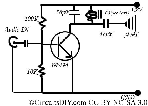
This is a simple and inexpensive FM transmitter. The circuit operates at a low voltage using a CR2025 3V battery with low current consumption. The total size of this FM transmitter, including the battery but excluding the antenna, is...
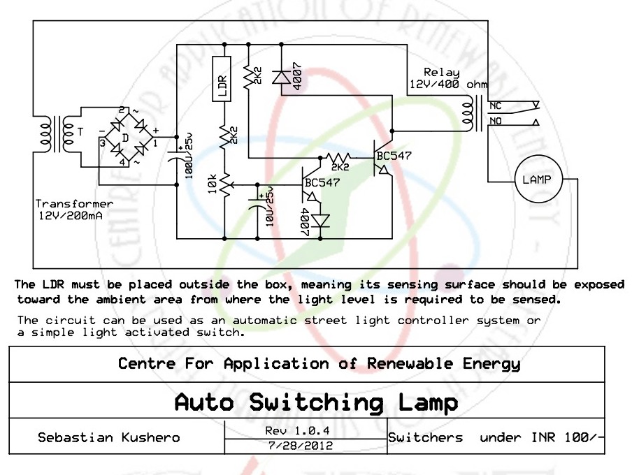
This sound-activated switch allows for sound control, which can be beneficial not only for robotic applications but also for home automation. The sound-activated switch operates by detecting specific sound frequencies or patterns, enabling the user to control various devices or...
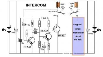
This is a two-station simple intercom circuit built using transistors and common 8-ohm mini speakers. The speaker functions as a microphone and generates sound, eliminating the need for a separate microphone in this intercom setup. The "press-to-talk" switches should...
This figure illustrates the schematic diagram of a simple inductance meter. U1 is a 74LS00 two-input quad NAND gate logic integrated circuit. Two resistors, a capacitor, and a surplus microprocessor crystal create a stable crystal oscillator operating close to...
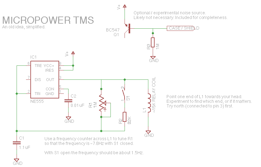
Let's face it, not every day is the greatest. Sometimes, one may not feel like doing much of anything. Wouldn't it be nice if there was a way to change brain waves at the push of a button? Transcranial...
It can drive up to 128 individual relays, solenoids, motors, fireworks, pyrophones, etc. With a MIDI note-on message you may switch on one of the 128 LEDs (or relays). Outputs may be switched off by sending a note-off message,...