
Simple RF Power Meter
To facilitate the measurement of output power in QRP (Low Power) transmitters, a straightforward circuit can be implemented using a multimeter and a precision resistor. The circuit's primary function is to measure the voltage drop across a known load resistor, which in this setup is specified as an 8k ohm resistor.
The multimeter should be set to measure voltage, as the output power can be calculated using the formula P = V²/R, where P is the power in watts, V is the voltage measured across the resistor, and R is the resistance value (8k ohms in this case). This approach allows the operator to determine the output power without complex instrumentation.
In the circuit, the 8k resistor should be connected directly in series with the output terminal of the transmitter. It is essential to position this resistor as close as possible to the output terminal to minimize any potential losses or variations caused by the lead resistance. The multimeter leads should then be connected across the 8k resistor to measure the voltage drop accurately.
For optimal performance, the multimeter used should have a high input impedance, ideally around 20k ohms per volt, to prevent loading the circuit and affecting the output power measurement. This high sensitivity is particularly important for low power transmitters, where even small variations can significantly impact the readings.
Once the voltage is measured, the output power can be calculated, providing valuable feedback to the operator regarding the transmitter's performance. This simple setup allows beginners to troubleshoot their QRP setups effectively and gain a better understanding of their equipment's operation.Many beginners trying out their skill with QRP TX, for the first time have to overcome many problems before they are able to come on the air. On usual complaint is that, every thing is working fine but the signal is not going out. Here is a simple set up which will enable them to measure the out put power of their transmitter. All that they require is a good multimeter which has a sensitivety of 20k ohms/4 Watts which is adequate for low power transmitters.
The 8k resistor should be kept close to the out put terminal of the transmitter. 🔗 External reference
Related Circuits
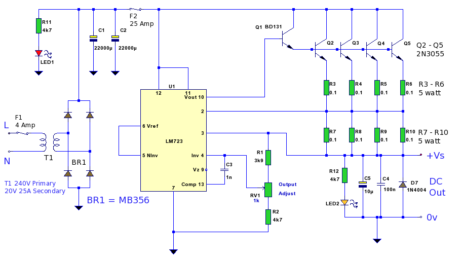
A 12 Volt high current 20 Amp power supply. The output voltage is variable from 12.2 Volt to 14.4V, allowing it to be set for any device requiring voltage and current within that range. This power supply unit (PSU)...
This simple circuit makes it possible to monitor the charging process to a higher level. If you need more information then check out the LM3914 Datasheet. Final adjustments are simple and the only thing needed is a digital voltmeter...
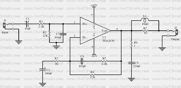
This simple 10 watts audio power amplifier is designed for home-brewed purpose. It is based on an Audio Power Amplifier IC that is called TDA2030. It is a monolithic integrated circuit in Pentawatt package, intended for use as a...
The copyright of this circuit is owned by Smart Kit Electronics. This document discusses improvements and modifications based on the original schematic. It describes a straightforward yet highly accurate and useful digital voltmeter designed as a panel meter, suitable...

I made this project as a test to improve a technique to read analog values without analog-to-digital converter (ADC). I ended with this "sound meter". It may not work perfectly, it needs some improvement but works anyway. It has...
A tachometer can be constructed using the TC9400 in frequency-to-voltage (F/V) mode to convert frequency information (RPM) into a linearly proportional voltage. This voltage can then be compared to one of several comparators (in this example, using eight). The...
Warning: include(partials/cookie-banner.php): Failed to open stream: Permission denied in /var/www/html/nextgr/view-circuit.php on line 713
Warning: include(): Failed opening 'partials/cookie-banner.php' for inclusion (include_path='.:/usr/share/php') in /var/www/html/nextgr/view-circuit.php on line 713