
Sound amplitude meter

This project involves the design of a sound meter that utilizes a microcontroller to read analog values without the need for a traditional analog-to-digital converter (ADC). The core of the circuit is based on a digital input/output pin configured to read the voltage levels generated by an electret microphone. The sound meter features an "auto-calibration" function, which allows it to automatically adjust its sensitivity based on the detected signal, thereby negating the requirement for an additional amplification circuit.
The circuit employs a resistor-capacitor (RC) network connected to a digital I/O pin. The choice of capacitor value can be either 10nF (103k) or 220nF; however, a polyester capacitor is recommended for optimal performance. The microcontroller code is compatible with the Microchip PIC16F84A and PIC16F628 models, with specific configuration settings for each. For the PIC16F628, the configuration should utilize an internal resistor-capacitor (RC) oscillator and enable Power-Up Timer (PWRT). Conversely, the PIC16F84A requires an external RC configuration with PWRT enabled.
To implement the analog reading technique, the following steps are executed: First, the RC circuit is connected to a digital I/O pin. The pin is then set as an OUTPUT and driven high for a duration of 1 millisecond. After this period, the pin is switched to INPUT mode, and a 16-bit counter is initiated. This counter runs until the voltage at the input pin drops low, at which point the counter's value is indicative of the analog signal level, reflecting the voltage across the RC circuit.
This method allows for a straightforward approach to analog value measurement, utilizing digital components and minimizing the complexity typically associated with ADCs. Further exploration and experimentation with capacitor values and configurations can enhance the performance of the sound meter, potentially leading to improved accuracy and responsiveness in various applications. For additional technical details and application notes, reference materials available on the Microchip website may provide valuable insights.I made this project as a test to improve a technic to read analog values without analog-to-digital converter. (ADC) I ended with this "sound meter". It may not work perfectly, it needs some improvement but works anyway. It have the feature of "auto-calibration", so it detects the signal, amplify it and measures it. Because the "auto-calibration" feature, it doesn't need an amplifier or any aditional circuit to drive the signal from the electret microphone.
The capacitor can be a 103k or a 220k. A poliester capacitor works better. The code is compatible con 16F84A or 16F628 so I can't define exactly what value should have. Anyway, If you find this projects interesting, you may be able to experiment with the value of the capacitor.
The config should be: INTERNAL RC and PWRT ON for 16F628. For the 16F84A the config is External RC and PWRT ON. As I mention before, the reason of this project is becuse i'm working in a technic to read analog values directly from a signal without an ADC. Here is the method used to read analog values with a digital input output pin: 1. Connect a RC circuit to a Digital I/O pin. 2. Set the pin as OUTPUT and make it high for 1 ms (one milisecond) 3. Set the pin as INPUT and start a 16 bit counter until the input signal is low. The value of the 16-bit counter should be the value of the input signal or the value of the RC. You can learn more about this technic at the Microchip's web page (www.microchip.com) reading the application notes at the documentation section.
🔗 External reference
Related Circuits
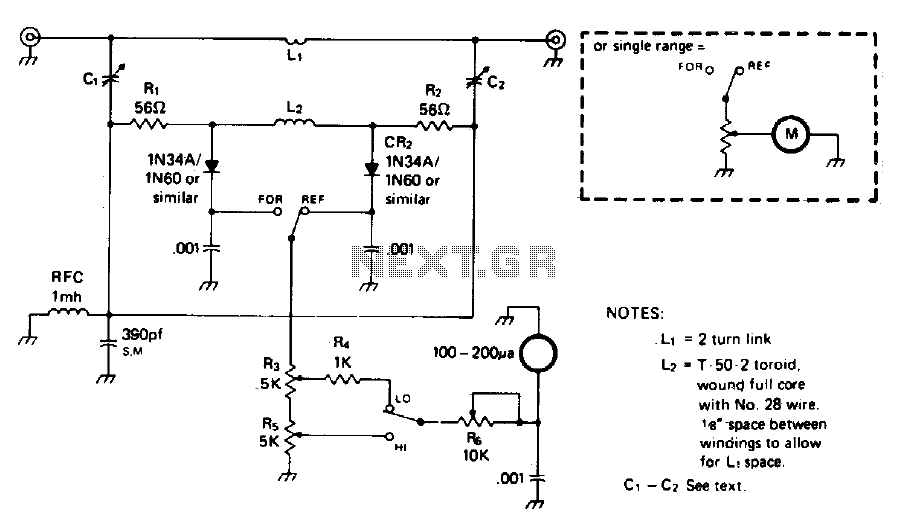
The circuit is not frequency sensitive. Its calibration will be accurate over a wide frequency spectrum, such as the entire amateur HF spectrum, if the values of L2, the voltage divider capacitors C1, C2, and C3, and the resistances...
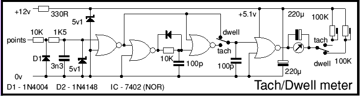
This circuit as first published in Wireless World September 1975 and subsequently in MECRM. It's built around a TTL quad NOR gate, though CMOS could be used. The circuit in question utilizes a TTL (Transistor-Transistor Logic) quad NOR gate, which...

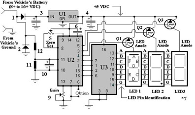
The multifunction frequency meter is an instrument that can measure various parameters on a single display using an 8-digit 7-segment LED. The controls measure... The multifunction frequency meter is designed to provide accurate measurements of frequency, voltage, current, and other...
To create a dashboard digital voltmeter circuit diagram that includes a parts list, PCB layout, and component placement, a full PDF article is available for download. The dashboard digital voltmeter circuit is designed to provide an accurate measurement of voltage...
This tester is designed to locate stray electromagnetic (EM) fields. It will easily detect both audio and RF signals up to frequencies of around 100kHz. Note, however that this circuit is NOT a metal detector, but will detect metal...
It consisted of 16 LEDs in a circle with two touch pads. By placing your fingers on the touch pads, the circuit started and ran the LEDs in a "chaser" pattern around the display, with a beep each time...
Warning: include(partials/cookie-banner.php): Failed to open stream: Permission denied in /var/www/html/nextgr/view-circuit.php on line 713
Warning: include(): Failed opening 'partials/cookie-banner.php' for inclusion (include_path='.:/usr/share/php') in /var/www/html/nextgr/view-circuit.php on line 713