
Simplest and low cost USB AVR
This documentation describes a simple open-source USB AVR programmer and SPI interface. It is low-cost, easy to assemble, works well with avrdude, is compatible with AVRStudio, and has been tested on Windows, Linux, and macOS X. It is suitable for students and beginners, and can serve as a backup programmer.
The project is based on the USBtiny code and design. Key improvements include modifications to allow it to function as a SpokePOV interface, the addition of low-level bit-bang commands, and the inclusion of a "USB good" LED. Other changes involve new VID/PID to make it official, the removal of some commands, and adjustments to pin arrangements.
This design can be constructed using the provided schematic and firmware, or a kit can be purchased from the Adafruit webshop. Having a complete kit available addresses the challenge of acquiring or building a USB programmer that requires an initial programmer to start the process (e.g., USBasp, AVRdoper, USBprog).
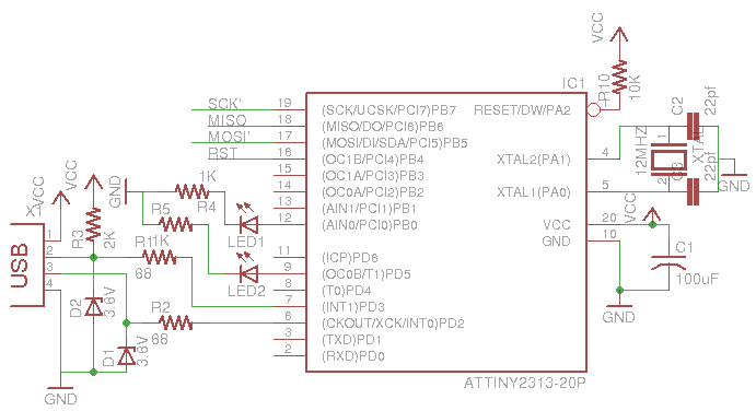
The AVR programmer utilizing the ATtiny2313 is designed to facilitate the programming of various AVR microcontrollers. The schematic typically includes essential components such as resistors, capacitors, and a USB interface, allowing for seamless communication between the programmer and the target microcontroller. The ATtiny2313 serves as the core microcontroller, managing the programming operations and interfacing with the host computer.
The circuit should be assembled carefully, ensuring that all connections are secure and that the components are placed according to the schematic. Proper attention should be given to the fuse settings, as these define the operational characteristics of the ATtiny2313, such as clock speed and startup time. The use of avrdude provides a command-line interface for programming, allowing for flexibility in various development environments.
In addition to the basic programming capabilities, the enhancements made to the original USBtiny design, such as the SpokePOV interface functionality and the low-level bit-bang commands, expand the usability of the programmer. The inclusion of a "USB good" LED serves as a visual indicator of successful USB communication, enhancing user experience.
For those who prefer not to build the programmer from scratch, the availability of a kit simplifies the process, ensuring that all necessary components are included. This approach mitigates the common issue of needing a programmer to program a programmer, making it accessible for beginners and hobbyists alike. Overall, this AVR programmer represents a valuable tool for anyone working with AVR microcontrollers, combining affordability and functionality in a compact design.This is the low cost AVR programmer using attiny2313. The schematic diagram is given below. First setup the circuit as shown. One important care taken to make fuse bit avrdude -c usbasp -p t2313 -U hfuse:w:0xdf:m -U lfuse:w:0xef:m If you use serial port to write the program , use stk200 command instead of usbasp.
Refer this site: https://learn.adafruit.com/usbtinyisp for to burn program to this attiny 2313
This is documentation for a simple open-source USB AVR programmer and SPI interface. It is low cost, easy to make, works great with avrdude, is AVRStudio-compatible and tested underWindows, Linux and MacOS X.
Perfect for students and beginners, or as a backup programmer.
The project is based off of the USBtiny code & design. The main improvements are: adjusting the code to allow it to act as a SpokePOV interface, adding lowlevel bitbang commands, and addition of a "USB good" LED.
Other changes are new VID/PID (to make it official), removing some of the commands, and moving around the pins a bit.
You can build this design using the schematic and firmware, or buy a kit from the Adafruit webshop. Having a full kit available solves the "chicken & egg" problem of purchasing or building a USB programmer that then needs a programmer of some sort to 'kick start'.
(See USBasp,AVRdoper, USBprog)
Related Circuits
This unique amplifier was designed and built for the European Triode Festival in 2007, focusing on "White Light" amplifiers that utilize thoriated tungsten tubes. Due to the impracticality of transporting a large tube amplifier from the US to Europe,...

STMicroelectronics introduces the STV0288, its latest DVB and DIRECTV QPSK digital receiver, which adds blind scan capability and DiSEqC 2.0 to the industry-leading STV0299 and provides a cost reduction path for new products. The STV0288 is a sophisticated digital receiver...

This circuit utilizes a CA018 BiMOS operational amplifier. A low current, supplied at the input potential as a power supply to the load resistor RL, is amplified by the resistor ratio R2/R1, while the load current h is monitored...
A 2003 Monte Carlo SS is experiencing issues with low idling, causing the engine to stall while driving or when parked. Additionally, the dashboard lights are malfunctioning; they occasionally activate for a brief moment before turning off again. There...
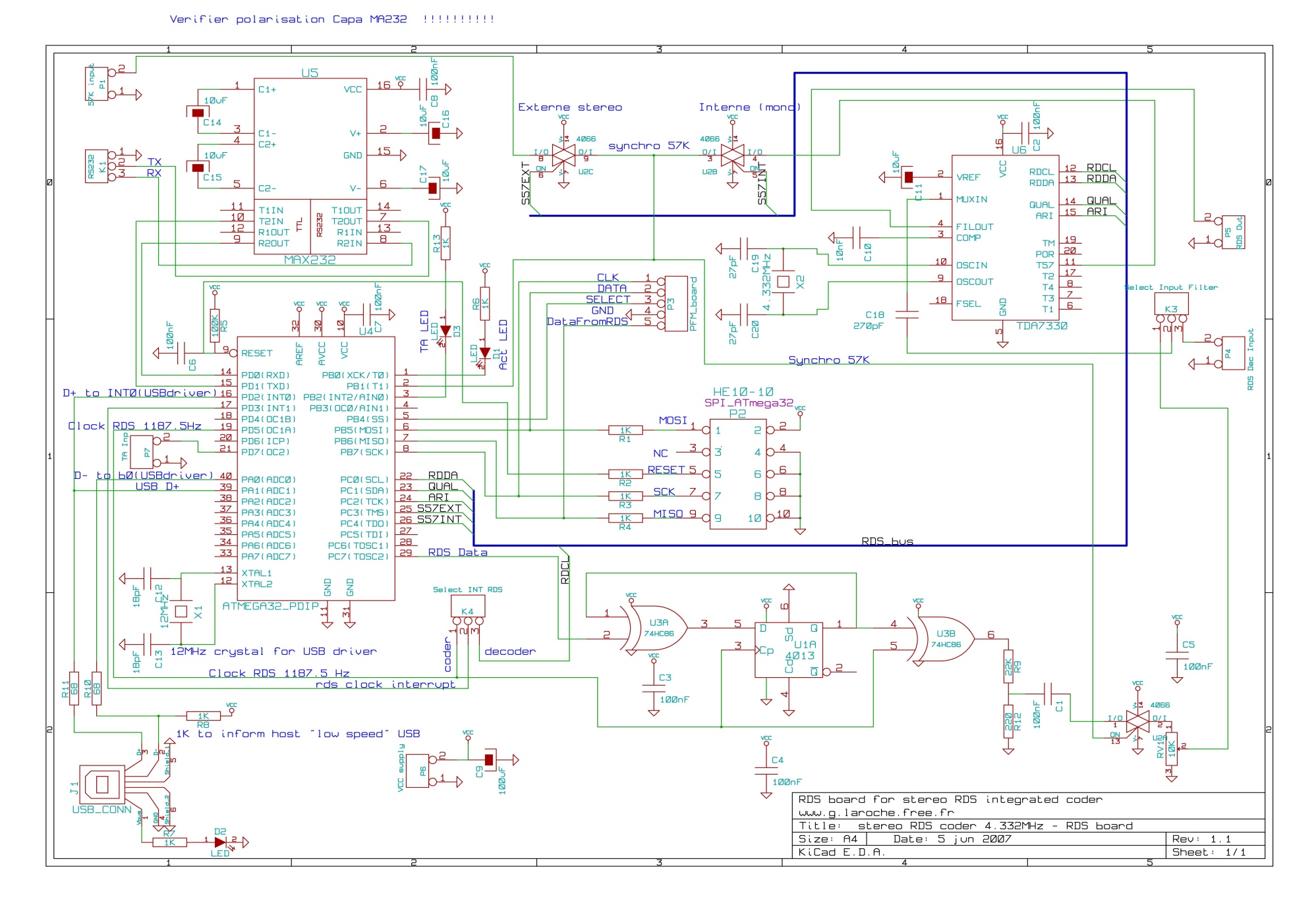
This board is an RDS coder utilizing an ATMEL AVR ATmega32 microcontroller. It can be controlled via an RS232 link, USB interface, or SPI. TA data is displayed with an LED and can be controlled through hardware input, RS232,...
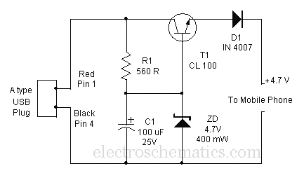
A mobile phone can be charged using the USB outlet of a PC. This simple USB cellphone charger circuit provides a regulated output of 4.7 volts for charging the mobile phone. The USB outlet typically supplies 5 volts DC...