
USB RDS Coder Board using ATmega32
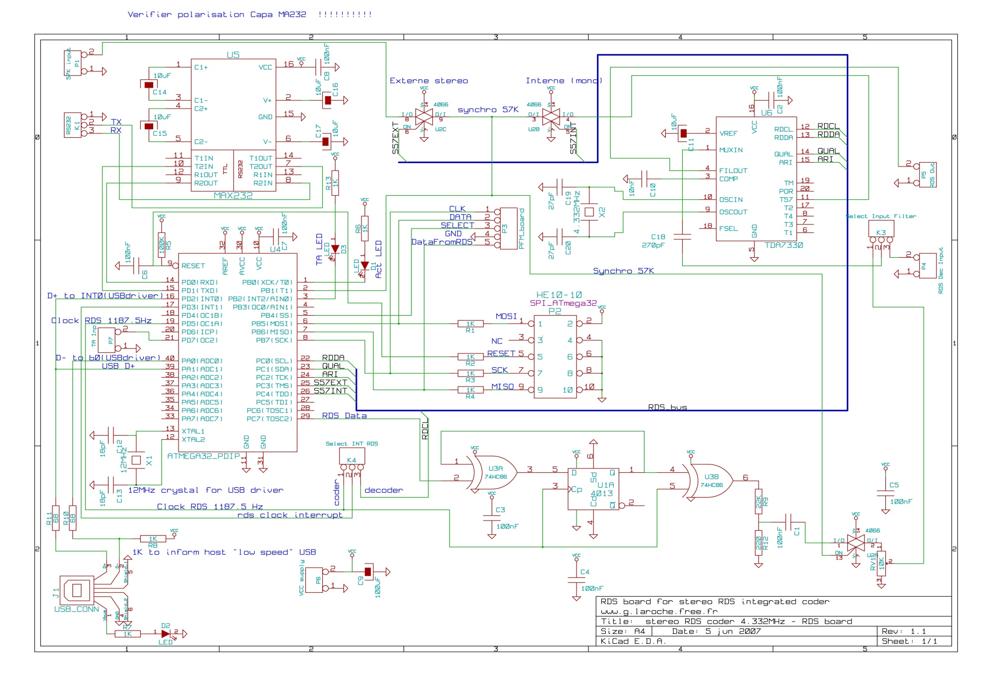
The RDS (Radio Data System) coder is designed to encode and transmit additional data alongside traditional FM radio broadcasts. The core of the system is the ATMEL AVR ATmega32 microcontroller, which provides the necessary processing power and control capabilities. This microcontroller features a 16 MHz clock speed, 32 KB of flash memory, and various input/output pins that facilitate interfacing with other components.
Control options for the RDS coder include RS232, USB, and SPI. The RS232 interface allows for serial communication with external devices, enabling configuration and data transmission. The USB interface offers a more modern and versatile connection option, allowing for easier integration with computers and other USB-capable devices. The SPI (Serial Peripheral Interface) is mentioned as a future enhancement, which will enable high-speed communication with other peripherals.
The board's functionality includes the display of Traffic Announcement (TA) data via an LED indicator, providing a visual signal to users when a TA message is being transmitted. The control methods for this data display include direct hardware input, which allows for manual operation, as well as through the RS232 and USB interfaces for automated or remote control.
Future enhancements for the board could include the implementation of the SPI interface, which would allow for additional peripheral connections, expanding the overall functionality and flexibility of the RDS coder. This could also enable the integration of more advanced features, such as real-time data processing and improved user interface options.This board is a RDS coder using an ATMEL AVR ATmega32. This board can be controled by a RS232 link, USB interface or SPI. TA data is displayed wiyth a LED and can be controled by : - Hardware input - RS232 - USB - SPI (not yet implemented).. 🔗 External reference
Related Circuits
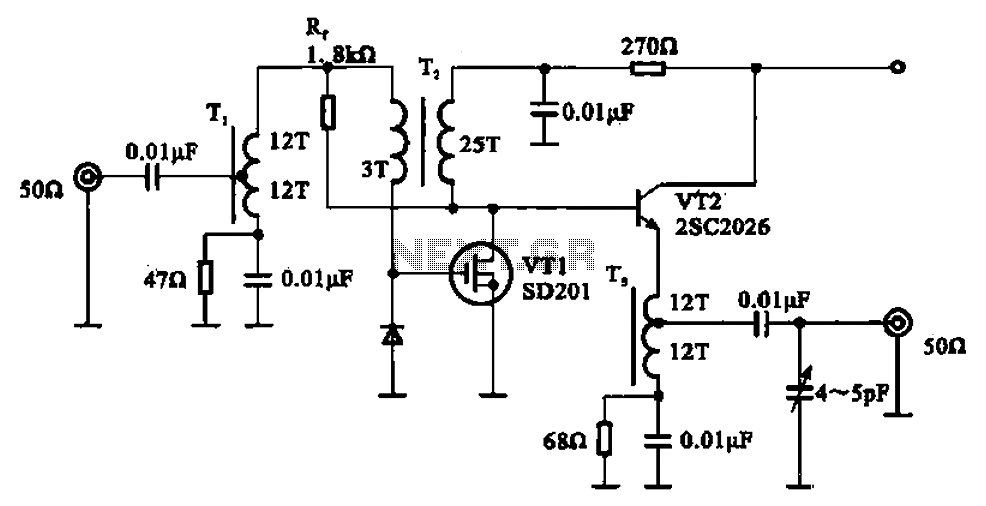
A broadband amplifier circuit utilizing a negative feedback amplifier configuration is presented. This circuit employs transformer coupling and a combination of amplifying sections and field-effect transistors (FETs). The input signal is applied to the center tap of the transformer...
The heart of the clock is a PIC 16f628A microcontroller. This microcontroller has an internal oscillator; however, an external 20MHz crystal oscillator is being used since it will have to accurately keep track of time for weeks and months....
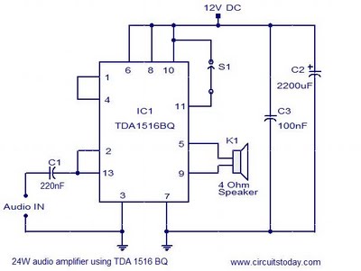
This document presents the circuit diagram of a simple 24W mono amplifier utilizing the TDA1516 integrated circuit. The TDA1516 is a Class B power amplifier housed in a 13-pin SIL package. It incorporates several beneficial features, including short circuit...
Probes or contacts may utilize a non-reactive metal. Gold or silver plated contacts from an old relay may be used; however, a cost-effective alternative is to wire alternate copper strips from a piece of veroboard. These will eventually oxidize,...
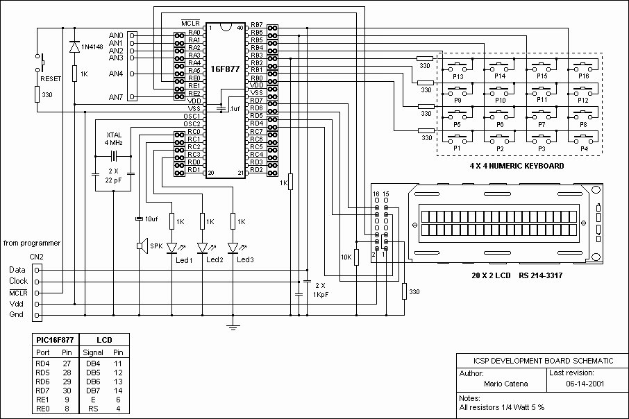
A schematic of a board featuring the PIC16F84 microcontroller, along with other compatible PIC microcontrollers that can be connected to the USB PICKit2 programmer. Additionally, there are concerns regarding the potential damage to the programmer when experimenting with oscillator...
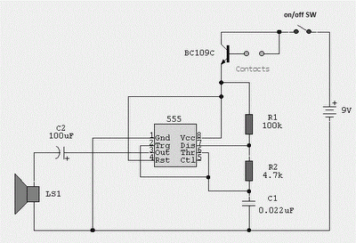
A simple pulse modulator circuit can be constructed using a 555 integrated circuit (IC). The 555 chip features a special modulator input located at pin 5. Below is the schematic diagram of the circuit. The pulse modulator circuit utilizing the...