
Single IC chip Motor Driver for robots
A motor driver is an essential component in robotic applications, particularly in mobile robots such as walkers. The primary function of a motor driver is to control the power supplied to the motors, enabling precise movement and control. In this context, the motor driver allows for the amplification of current, which is crucial when the existing circuit cannot provide sufficient power to drive the motors effectively.
The described motor driver circuit utilizes the ALS245 integrated circuit, which is a dual-channel, high-speed, bidirectional level shifter and buffer. Each ALS245 can supply a maximum output current of 50mA, which may be inadequate for applications requiring higher power. Therefore, to achieve the necessary current levels for driving motors, multiple ALS245 units can be stacked together. By stacking two ALS245 chips, the total output current is effectively increased to 100mA. However, for most applications, this may still fall short of the required power, necessitating the stacking of additional drivers. It is generally recommended not to exceed three stacked units, as this provides a balance between power requirements and circuit complexity.
In practical implementation, the motor driver connections are straightforward. The user is instructed to identify the motor connections, denoted as (M), and connect them to the input terminals of the motor driver. This configuration allows for direct control of the motor's operation through the driver, thus facilitating enhanced performance.
When designing a circuit with this motor driver, it is crucial to ensure that the power supply can accommodate the total current drawn by the stacked drivers and the motors. Additionally, proper thermal management should be considered, as increased current can lead to heating in the drivers, which may affect performance and reliability. Overall, this motor driver setup provides a flexible and effective solution for driving motors in robotic applications, particularly when higher current levels are required.A motor driver! I'm sure you knew that already but that's what it is. A motor driver is required in pretty much all walkers including all of my CW series walkers. You need to use it any time you need to supply more current to the motors because the circuit can't supply enough. I like this one because it's very easy to build and pretty flexible on what you can do with it. Just find the (M) and take the two connections going to it and hook them to the inputs of the driver.
Stack 'em up Q - When I hook my motor directly to the battery it has lots of power but when I hook it to the motor driver it doesn't and can't even move my walkers leg. A - Each driver supplies 50mA and since they are already doubled up you have 100mA which in most cases is not enough. The answer, stack 'em. You can see in the image on the right that all you have to do is stick another ALS245 on top and solder it on.
It's that easy. You can stack as many as you need but you shouldn't need more than 3 and 2 should be plenty. 🔗 External reference
Related Circuits
If an application utilizes a MOSFET to switch a load, it is straightforward to incorporate short-circuit or overload protection. This can be achieved by leveraging the internal resistance RDS(ON), which generates a voltage drop proportional to the current flowing...
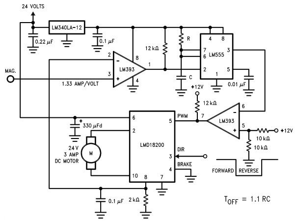
The LMD18200 3A H-Bridge, designed by National Semiconductors, can be used to create a simple motor controller electronic project suitable for motion control applications. This component is ideal for driving both DC and stepper motors, accommodating peak output currents...
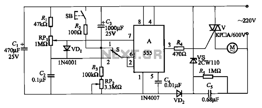
The circuit illustrated in Figure 3-12 incorporates variable speed and timing control functions. When switch S is set to position 1 and button SB is pressed, the motor initiates operation. After a predetermined delay, the motor automatically shuts down....
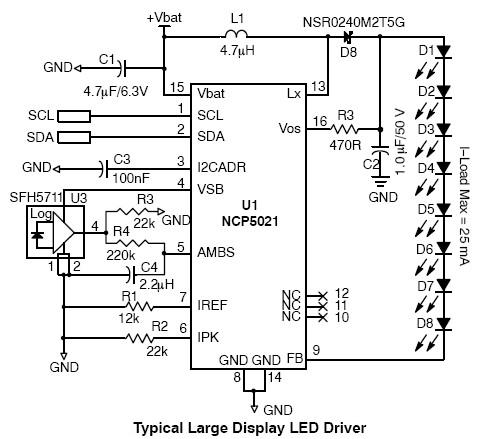
This high-voltage white LED driver electronic circuit schematic utilizes the NCP5021 integrated circuit from On Semiconductor. The NCP5021 is designed with an ambient light sensing feature and can drive up to eight LEDs in series for portable backlight applications....
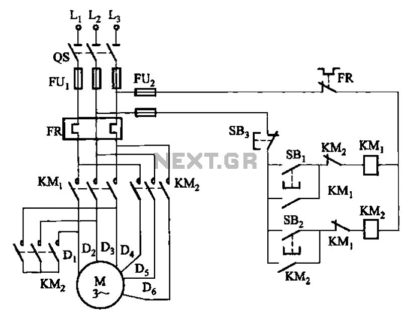
The circuit illustrated in Figure 3-97 features two contacts and is designed specifically for a 2kW dual-speed motor. In this configuration, SB1 is utilized for low-speed operation, while SB2 serves as the high-speed run button. The circuit operates by allowing...
Most of the CDROMS available have an Audio-Out Output to either plug in the headphones or connect it to an amplifier. This circuit enables one to use the CDROM as a stand alone Audio CD player without the computer....