
2Y- connection two-speed motor contactor control circuit 2
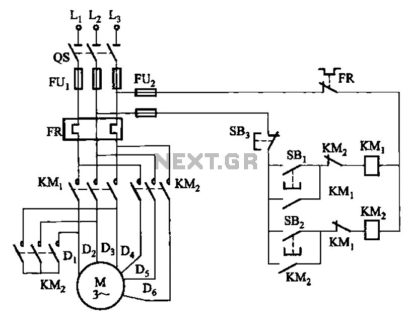
The circuit operates by allowing the user to select between two distinct speed settings for the motor, enabling efficient performance based on the application's requirements. The low-speed setting, activated by the SB1 button, is typically used for tasks that require more torque and less speed, making it suitable for applications such as starting heavy loads or operating machinery that benefits from controlled acceleration. Conversely, the high-speed setting, engaged through the SB2 button, facilitates faster operation, ideal for tasks that require quick movement or reduced processing time.
The two contacts in the circuit serve as switches that control the flow of current to the motor, effectively changing its operational speed. The design ensures that only one speed can be active at a time, preventing potential damage to the motor or the circuit itself. This is often achieved through a simple relay or contactor mechanism that engages the appropriate speed setting based on the button pressed.
In summary, the circuit in Figure 3-97 represents a straightforward yet effective solution for controlling a dual-speed motor, optimizing its performance for varying operational demands. The clear distinction between low and high-speed operation, facilitated by the respective buttons, enhances usability and operational flexibility. Circuit shown in Figure 3-97. The circuit only two contacts, the circuit is simple, but only applies to the following 2kW dual speed motor. Figure, SBi is running at low speed button, SBz high-speed run button.
Related Circuits
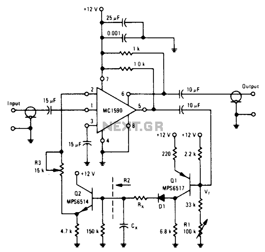
An amplifier designed to achieve a voltage gain of approximately 20, utilizing the MPS6517 PNP transistor in the emitter follower configuration. The RI controller allows for adjustment of the transistor's quiescent point. The output signal is activated only when...
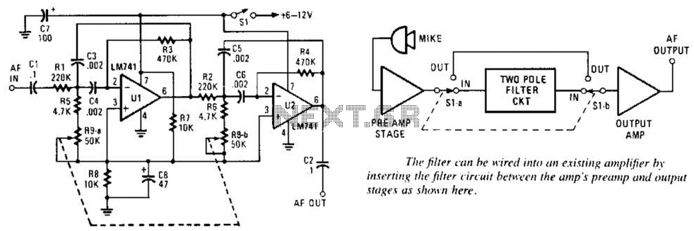
This variable-frequency audio bandpass filter is constructed using two 741 operational amplifiers (op amps) connected in cascade. Both op amps are configured as identical RC active filters, enhancing the selectivity of the overall circuit. The filter has a tuning...
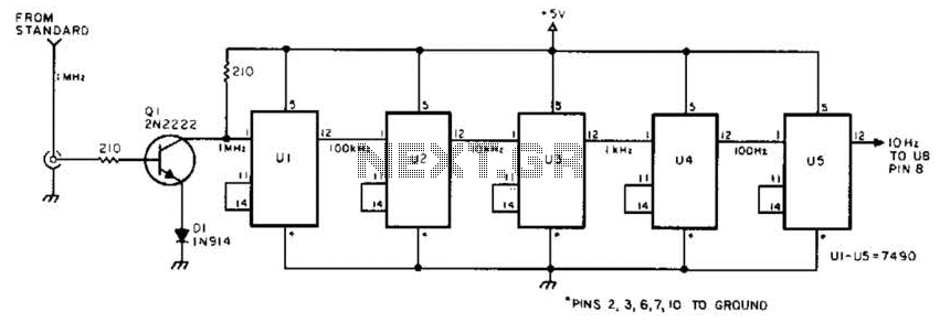
This circuit is designed to be driven by a 1-MHz standard signal with an amplitude of several volts. The components U1 through U5 are 7490 decade counters/dividers, providing a division ratio of 100,000:1. It is possible to tap off...
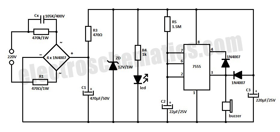
This is a simple power resumption alarm circuit that can be installed within the switch box. It emits beeping sounds when power is restored following a power failure. The power resumption alarm circuit is designed to provide an audible alert...
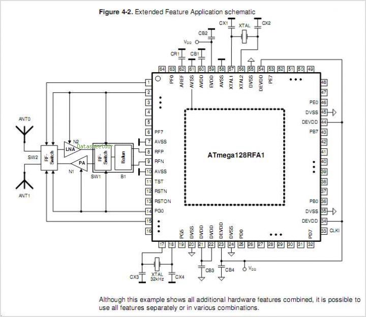
The ATR0981 is a monolithic integrated circuit (IC) produced using Atmel's advanced SiGe technology. This IC serves as a transmit and receive front-end solution, specifically designed for operation within a frequency range of 300 MHz to 500 MHz. It...
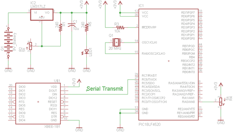
There are two schematics to examine for constructing a transmitter/receiver system. The first schematic is the transmitter, featuring a variable trimpot connected to RA0. The trimpot's value will be transmitted from the Tx pin of the PIC to the...