
Sinusoidal Oscillators
a. Condition for Oscillation: Using an ohmmeter, adjust the potentiometer of R4 to the calculated value from preliminary question 3, and activate the circuit. Alter the potentiometer setting and observe the effect on the oscillation waveform. Identify the setting of R4 that produces the most sinusoidal output and the value at which R4 just sustains oscillation. Verify with an ohmmeter and compare to the calculated value.
b. Rate of Build-Up of Oscillation: Modify the circuit as shown in figure 5. The transistor Q1 functions as a switch, halting oscillation when the square wave generator output is positive. When the generator output shifts to negative, oscillation begins to build up, which can be monitored on an oscilloscope triggered at this point. Adjust the time base until the build-up is observable on the screen. Analyze the effect of R4 on the build-up rate. Define rise time as the duration required for the output to reach ±10 volts in magnitude and determine the rise time for R4 values of 2k, 2.5k, 3k, 3.5k, 4k, 4.5k, 5k, and open circuit. Compare these measurements with the theoretical time constant of build-up, noting that the two values should be proportional.
c. Steady State Oscillation: Revert the circuit to its original configuration and observe the oscillator output. Adjust R4 and note the resulting waveform changes. Open R4 to examine the waveform. Investigate the cause of the waveform alterations and determine the optimal R4 value concerning distortion. Conduct a PSpice simulation of the circuit in Figure 2, assuming a 0-degree phase for the input V2. Plot the phase at nodes 1, 2, 3, and 4, along with the magnitude of V1 as a function of frequency, over a frequency range from 10 Hz to 1 MHz.
The described circuit serves as an oscillator, where the balance of feedback paths is critical for stable oscillation. The Wien-bridge oscillator is particularly noted for its simplicity and effectiveness in generating sine waves. The interaction between the resistive and reactive components determines the frequency of oscillation, while the feedback network ensures that the output remains stable and sinusoidal. The adjustments made to R4 allow for fine-tuning of the oscillation amplitude and waveform quality, while the use of an oscilloscope provides real-time observation of the oscillation characteristics. The PSpice simulation further aids in understanding the circuit's behavior across a range of frequencies, providing valuable insights into the phase relationships and magnitude responses in the oscillator's operation.If a linear feedback amplifier contains reactive elements, and at some frequency the loop gain Ab = -1, sinusoidal oscillations will be obtained. The sine wave oscillators investigated in this experiment consist essentially of two separate but connected parts; the amplifier part and the frequency determining part.
Probably the simplest type of feedback oscillator is shown in figure 1 . Here the amplifier function is the ratio, V2 / V1 = - R2 / R and through the phase shift circuit, the ratio V1/V2 is a function of frequency. In other words the amplifier yields a phase inversion of 180 ° and a 180-degree phase-shift-circuit is used to produce a zero loop phase shift.
An oscillator circuit in which a balanced bridge is used as the feedback network is the Wien-bridge oscillator shown in figure 3. The "bridge" is clearly indicated in figure 4. The four arms of the bridge are Z1, Z2, R3 and R4. The input to the bridge is the output Vo of the op. amp. , and the output of the bridge between nodes 1 and 2 supplies the differential input to the op. amp. There are two feedback paths in figure 3, positive feedback through Z1 and Z2, whose components determine the frequency of oscillation, and negative feedback through R3 and R4, whose elements effects the amplitude of oscillation.
The loop gain is given by -b A where: The maximum frequency of oscillation is limited by the slew rate of the amplifier. Continuous variation of frequency is accomplished by varying simultaneously the two capacitors. Changes in frequency range are accomplished by switching in different values for the two identical resistors R1 and R2.
a. Condition For Oscillation: With an ohmmeter, adjust the potentiometer of R4 to the calculated value in preliminary question 3, and turn the circuit on. Vary the potentiometer setting and note the effect on the oscillation waveform. At what setting of R4 does the output appear most sinusoidal What R4 just sustains oscillation. Check with an ohmmeter and compare with your calculated value. b. Rate Of Build Up Of Oscillation: Modify the circuit as shown in figure 5. The transistor Q1 acts as a switch and stops the oscillation when the square wave generator output is positive.
When the generator output goes negative, oscillation begins to build up. The scope is also triggered at this point. So the build up can be observed. Vary the time base until the build is visible on the screen. What is the effect of R4 on build up rate If a rise time is defined as the time required for the output to reach ±10 volts in magnitude, determine the rise time for R4 = 2, 2. 5k, 3k, 3. 5k, 4k, 4. 5k, 5k, and ¥ (open circuit). Compare these values with the theoretical time constant of build up. The two values should be proportional. c. Steady State Oscillation: Return the circuit to the original configuration; and observe the oscillator output.
Vary R4 and note the effect. Open R4 and observe the waveform. What is causing the change in waveform What is the best value of R4 in terms of distortion Do a PSpice simulation of the circuit in Figure 2. Assume 0 ° phase for the input V2. Plot the phase at nodes 1, 2, 3, 4 and the magnitude of V1 as a function of frequency. Plot over a frequency interval of 10 Hz to 1 MHz. 🔗 External reference
Related Circuits
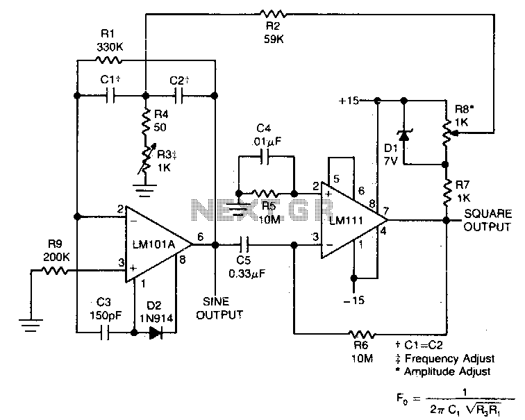
This circuit will provide both a sine and square wave output for frequencies ranging from below 20 Hz to above 20 kHz. The frequency of oscillation can be easily adjusted by changing a single resistor. This circuit is designed to...
The RF design and construction of radio frequency oscillators. Radio frequency (RF) oscillators are essential components in various electronic systems, generating signals at specific frequencies used for communication, signal processing, and other applications. The design of RF oscillators involves several...
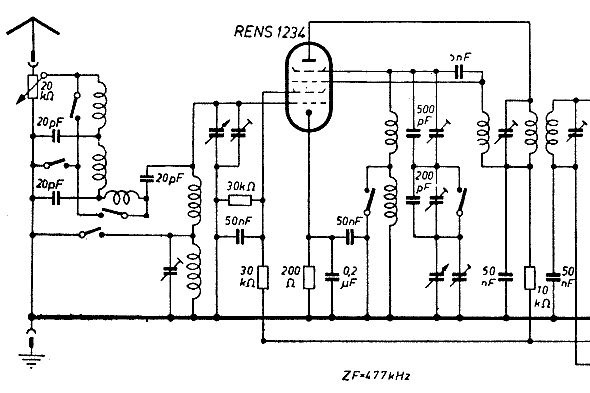
The schematic of the mixer section illustrates an oscillator. The oscillator's LC circuit has only two connections to the valve and does not include a tap or tickler coil. Oscillations will only occur if the tube provides a negative...
RC oscillators utilize resistors and capacitors to produce low or audio-frequency signals. Therefore, they are often referred to as audio-frequency (A.F) oscillators. RC oscillators are fundamental circuit designs utilized in various applications for generating periodic waveforms, particularly in the audio...
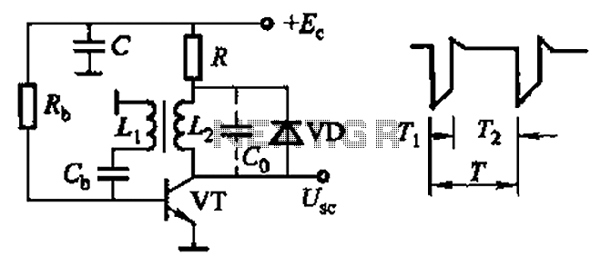
Common non-sinusoidal oscillator circuit, waveform and frequency formula - sawtooth oscillator - use blocking oscillator The sawtooth oscillator is a type of non-sinusoidal oscillator that generates a waveform characterized by a linear rise in voltage followed by a rapid drop....
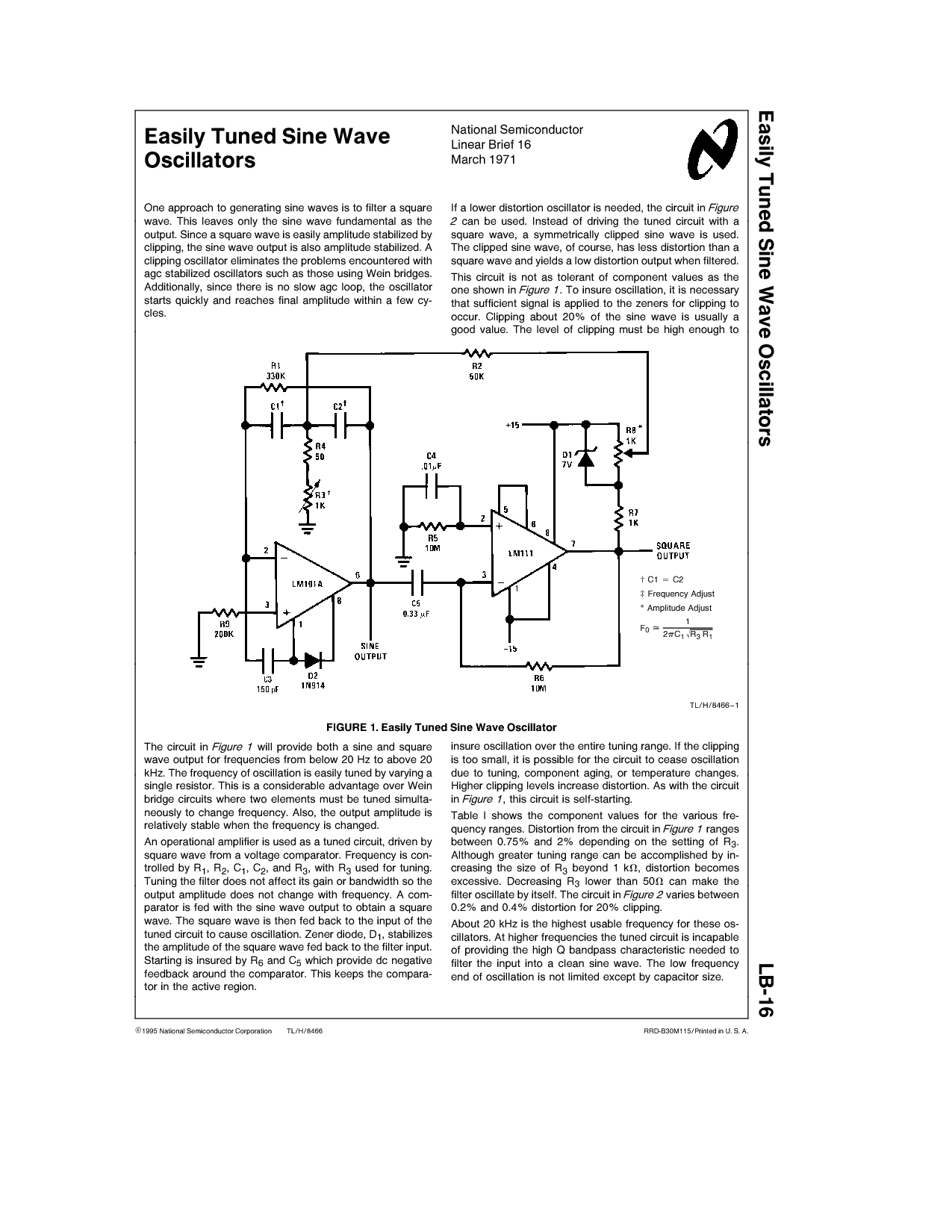
One approach to generating sine waves is to filter a square wave. This leaves only the sine wave fundamental as the output. If a lower distortion oscillator is needed, the circuit in Figure 2 can be used. Instead of...