
Siren Police Tone Circuit
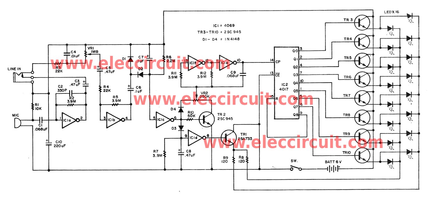
The police tone siren circuit typically utilizes a 555 timer IC configured in astable mode to generate a square wave output, which simulates the sound of a police siren. The frequency and duty cycle of the output signal can be adjusted using variable resistors VR1 and VR2.
In this circuit, the 555 timer is powered by a suitable DC voltage source, often ranging from 5V to 15V, depending on the specific requirements of the siren. The output from the timer is connected to a power amplifier stage, which drives a loudspeaker or siren unit, producing the audible sound.
The timing components, including resistors and capacitors, are selected to set the desired frequency of the siren tone. The use of variable resistors allows for fine-tuning of the sound, enabling the user to achieve the characteristic rising and falling pitch associated with police sirens.
Proper layout and grounding techniques should be employed in the circuit design to minimize noise and ensure reliable operation. Additionally, protection components such as diodes may be included to safeguard the circuit from voltage spikes generated by the inductive load of the speaker.
Overall, this circuit serves as an effective solution for simulating a police siren tone, suitable for various applications in alarm systems or educational projects.Here is police tone circuit of siren. this simple and very easy to make it. vr 1 and vr 2 for change delay sound of siren. simple and easy. if sound output not. 🔗 External reference
Related Circuits
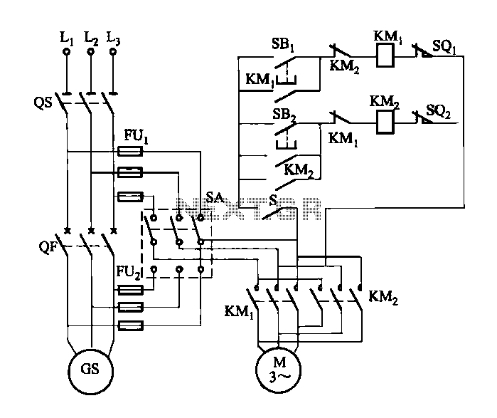
FIG M is a variable speed motor control for the opening and closing of a wicket gate. It features an electric governor. The system is activated by a power switch (SA) located on the front grid, and a toggle...
Individuals seeking a distinctive gift for Christmas and New Year may find this project appealing. Certification of this project will undoubtedly create a preference for it. The project in question appears to be a creative endeavor aimed at providing a...
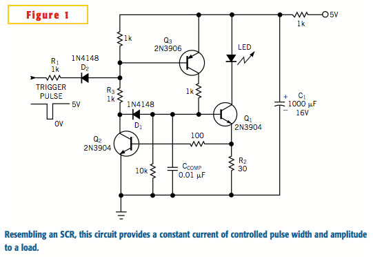
A typical silicon-controlled rectifier (SCR) requires a trigger current to latch on. Once the device is latched, the current flowing through the SCR is determined only by the external component values. The SCR lacks the ability to limit current...
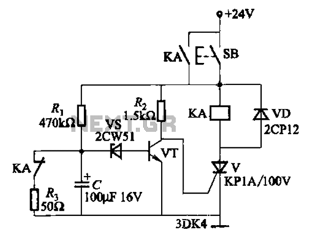
This circuit is a thyristor-based delay circuit known as a cut-off delay. It allows for a specified delay period after the thyristor is activated. The delay time of the circuit can be adjusted within 10 seconds by changing the...
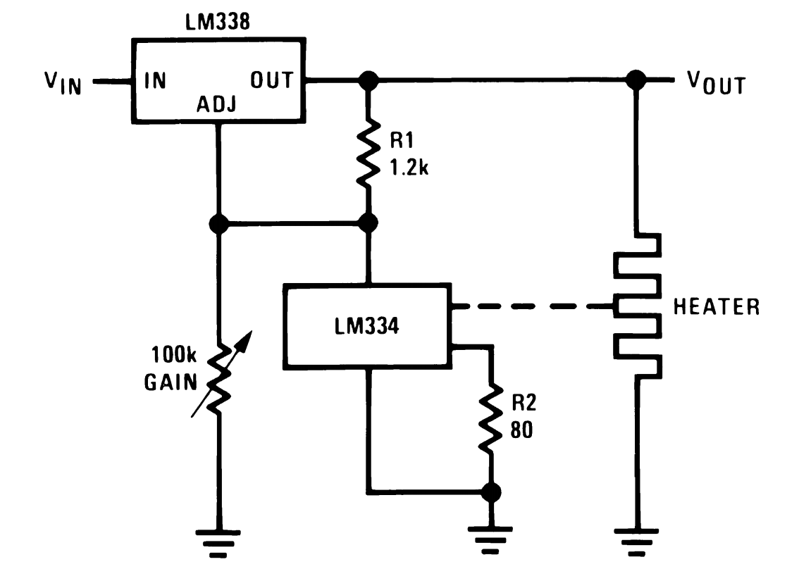
This power supply utilizes a single 7812 IC voltage regulator along with multiple external pass transistors, enabling it to deliver output load currents of up to 30 amps. The circuit design incorporates a 7812 linear voltage regulator, which is...
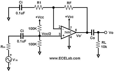
All the capacitors are present to block DC signals; however, the values of capacitance are crucial, and it is necessary to determine the value of Co. Rin denotes the source resistance, which is not an integral part of the...