
Motor Speed and Speed protection circuit of small hydropower stations
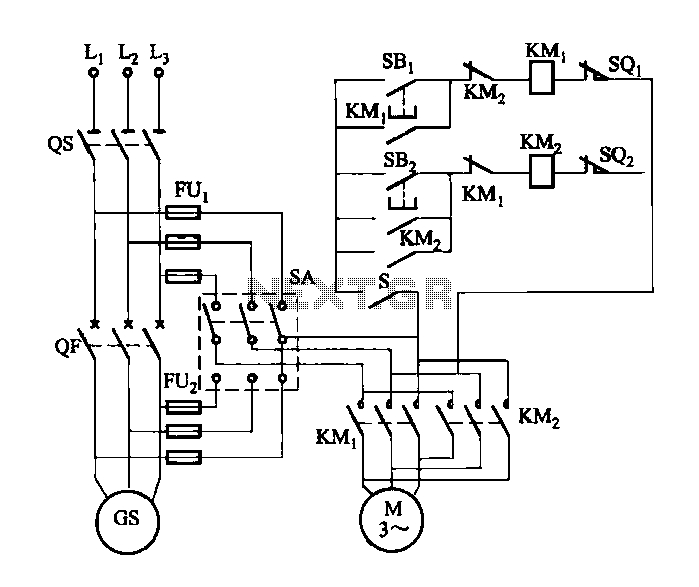
The variable speed motor control system for the wicket gate is designed to manage the precise operation of the gate through a combination of switches and limit sensors. The power switch (SA) initiates the control system, allowing for the toggling of switch (S) to enable the motor operation. The integration of an electric governor ensures that the motor's speed is regulated according to the operational requirements of the generator.
The system incorporates several safety features to protect both the motor and the generator. The limit switch (SQi) serves as a critical component, halting the motor when the generator reaches full load conditions, thereby preventing potential overload situations. Similarly, the operation of the turbine guide vane is monitored by limit switch (SQ), which stops the motor when the gate is fully closed, ensuring that the system does not operate outside its designed parameters.
In the event of a generator failure, the circuit breaker (QF) plays a vital role in the protection mechanism. Upon tripping, the auxiliary contact of the circuit breaker closes, which energizes contactor (KMz). This action causes the motor to reverse its direction, allowing the wicket gate to return to a safe position until limit switch (SQz) indicates that the gate is fully open, thus completing the emergency shutdown sequence.
Overall, the design of this motor control system emphasizes reliability and safety, utilizing a combination of mechanical and electrical components to ensure effective operation while minimizing risks associated with generator and motor failures.FIG, M is a variable speed motor control wicket opening and closing and opening. O electric governor. Front grid, hit the power switch SA A side, toggle switch S is opened; aft er the grid, SA play and be in the generator side, S is closed, the trip in order to achieve self-protection purposes. When the generator grid, with full load, limit switch off SQi top open, the motor is stopped; when off, when the turbine guide vane opening is zero, the limit switch so: the top open, the motor is stopped.
Speed protection. When the generator fails, tripping the circuit breaker QF, its auxiliary contact is closed, the contactor KMz was electric pull, reverse the motor until the limit switch sQz top open, shut down is completed.
Related Circuits
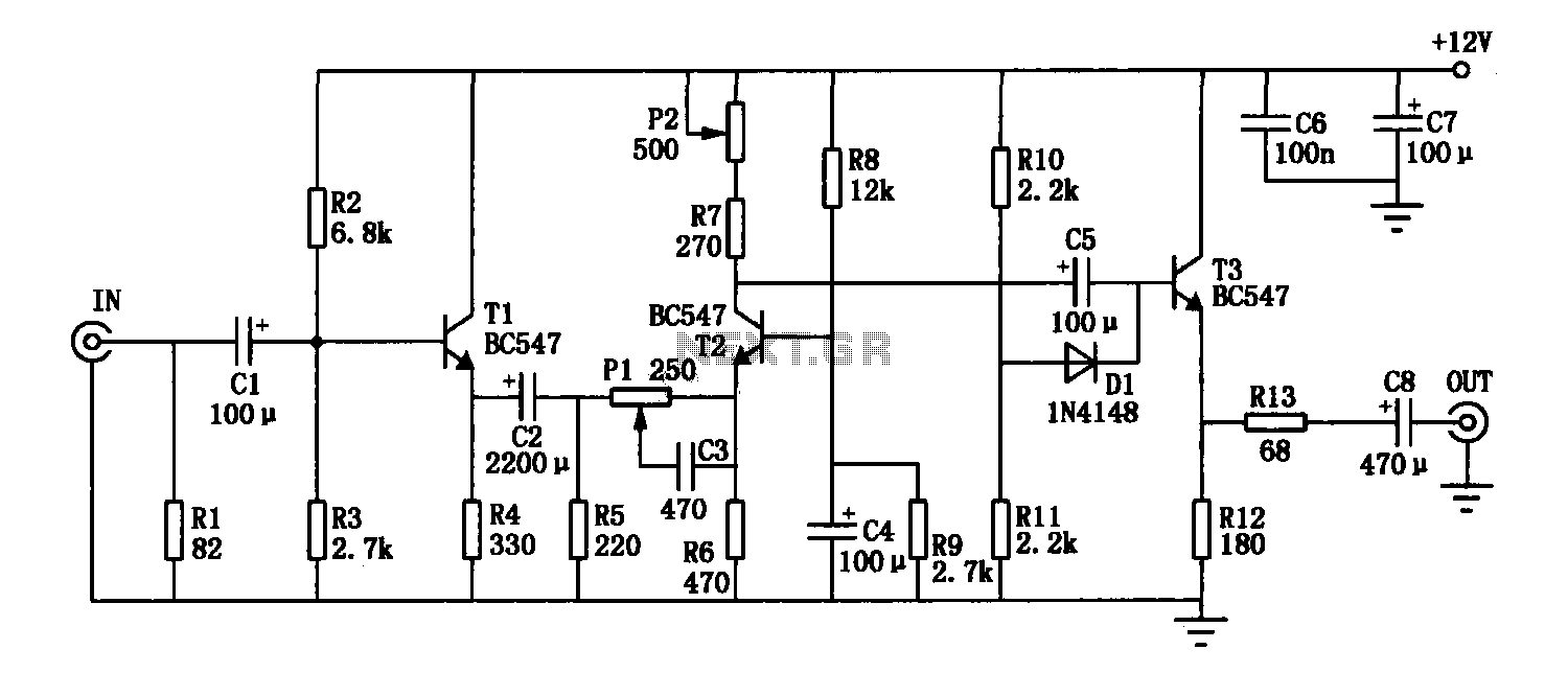
The enhancement circuit, as depicted, increases the high-frequency components of the video signal, thereby improving the contrast of the television image. It can be connected between the VCR and the TV SCART input. The circuit utilizes transistor T1 for...
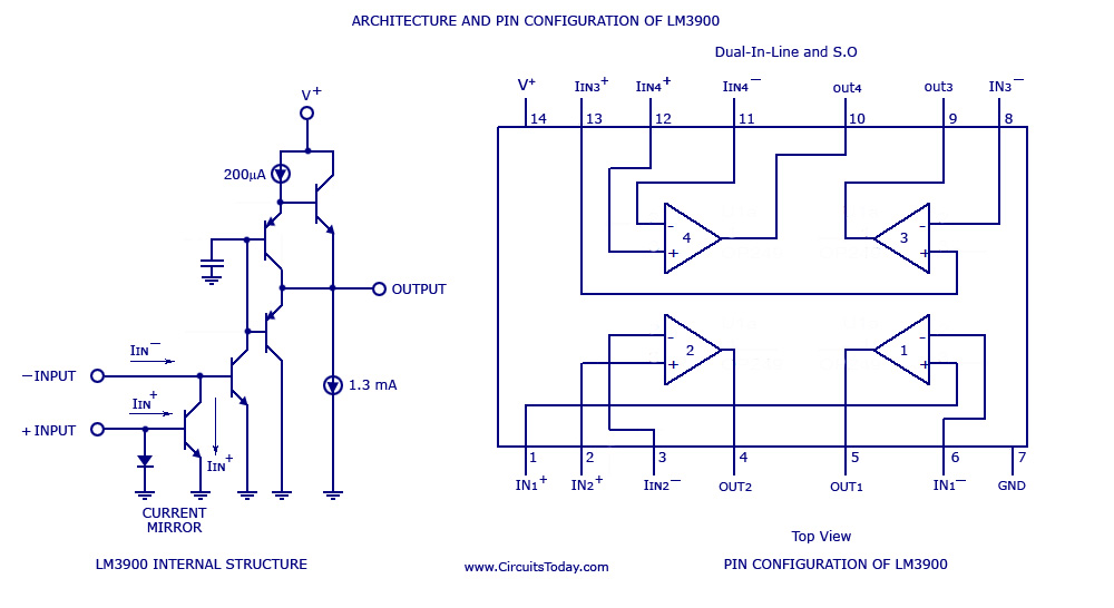
A simple multi-channel audio mixer circuit utilizing the LM3900 quad amplifier is presented below. The circuit features a four-channel quad amplifier (LM3900) with two microphone audio inputs and two direct line inputs. By paralleling additional circuits, the number of...
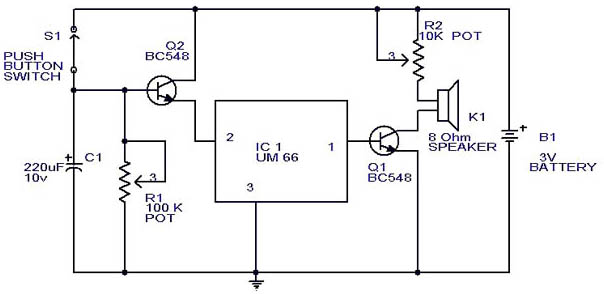
This circuit is a slight modification of a previous design. In the earlier version, the switch needed to be held down for the entire duration of the music playback. In this updated circuit, pressing the push button once charges...
The electronic designs for the two animatronic mouths are presented below. The first design is for the articulated mouth, with additional servos for the eyebrows and eyes. The second design is for the LCD mouth, which closely resembles the...
The EQ-2 is a 6-band graphic equalizer circuit. Each band is controlled by potentiometers RV1-6, which are designed as faders for improved visual indication of adjustments. However, standard potentiometers can also be used as replacements. At the center position...
The Audio Automatic Gain Control (AGC) circuit monitors the output signal level of an audio preamplifier. When the input signal increases, the AGC circuit automatically reduces the amplifier's gain. Conversely, when the input signal decreases, the AGC circuit increases...