
Small Vacuum tube Tesla coil (VTTC)
")
The VTTC circuit operates by utilizing a class C Hartley oscillator, which is a common configuration for generating high-voltage outputs. The oscillator consists of a tank circuit formed by the resonant capacitor and the primary winding of the transformer, which resonates at a specific frequency determined by these components. The use of a non-standard multiplier for the anode supply enhances the voltage available for the oscillator, allowing for higher peak voltages necessary for effective operation.
The thyristor-based interrupter plays a crucial role in modulating the output of the Tesla coil. By controlling the timing of the discharge through the primary winding, the interrupter can create a staccato effect, which increases the efficiency of energy transfer to the secondary winding and enhances the length of the output streamers. This tuning process is critical and requires careful adjustment to achieve optimal performance.
The choice of vacuum tubes such as the PL500, PL36, or PL504 is significant due to their ability to handle high voltages and currents reliably. These tubes are designed to operate in high-stress environments typical of television deflection circuits, making them suitable for the demands of a Tesla coil. The inclusion of a fuse in the cathode connection is a prudent safety measure, protecting the tube from potential damage due to misconfiguration or tuning errors.
In summary, this portable Tesla coil design exemplifies a balance between functionality and safety, making it an effective choice for experimentation with high-voltage applications in constrained environments. The careful selection of components and circuit design principles ensures reliable operation and the potential for impressive electrical output.To go along with flyback drivers, X-rays and other high voltage stuff, I have decided to build myself a Tesla coil. Because I live in a flat though, there would be no place to accomodate and run monstrous coil designs, not mentioning interference, so that is the reason why I`ve opted for small and sweet portable setups like this one is.
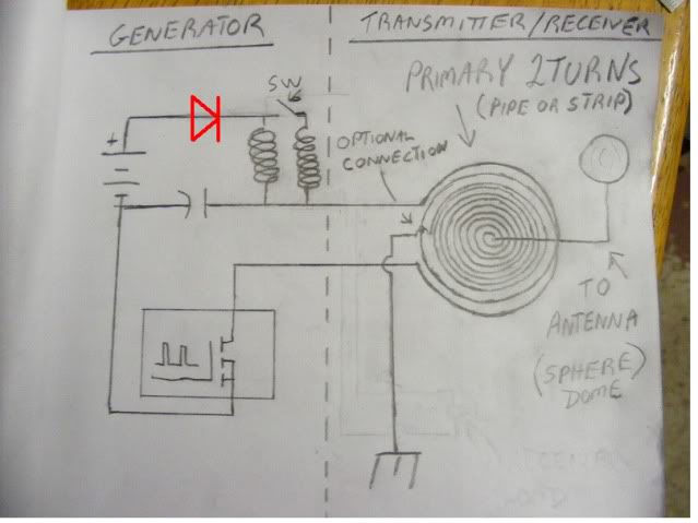
Behold! I had been in a dilemma in which topology should I`ve went for. Nikola Tesla`s original creation the spark gap Tesla coil has its advantages at high input powers; transistorized (solid-state) Tesla coils need a good driving circuit and are more prone to failure, but since at the time I had been making this coil one of my sources for obtaining electronic parts were black and white tube television sets; I have chosen the vacuum tube (VTTC) design, as vacuum tubes are mostly foolproof and sturdy at high voltages and don`t need special driver circuits. The basis for almost every VTTC is a class C-Hartley oscillator. Here, the anode supply is obtained from mains through a multiplier wired in a bit non-standard way, to increase peak-to-peak voltage.
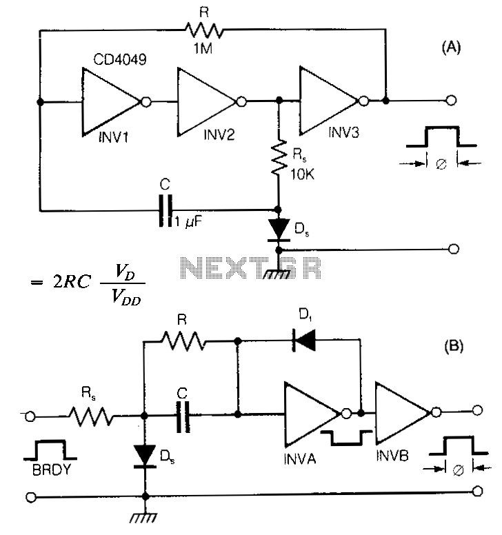
At this power output, the resonant capacitor is nothing unusual; a parallel connection of a few nice foil ones rated 0n5 is going to do the trick. To increase efficiency and decrease input current draw, there`s a thyristor (SCR)-based interrupter (staccato) circuit, which when properly tuned gives sword-like streamers double in length (7 cm) !
The tube which is used in my setup comes from a horizontal deflection circuitry of a B&W television set. I`m using a PL500 made by RFT, but with any similar pentode tubes like PL36 (EL36), PL504 you`re good to go.
These were extensively used in every European black and white televisions through the 60s-70s. However if you happen to have a PL509, EL509 or its Soviet equivalent 6P45S, it is easy to get 20 cm streamers with a microwave oven transformer supply and a good resonant cap. You might have noticed a fuse in the cathode connection, as presented in the above schematic. Well, this circuit has some unfortunate consequences with some PL504s: when mistuned (too little or too many feedback turns), sometimes the circuit abruptly stops oscillating and grabs a huge inrush current which ruptures the thin internal cathode connection, rendering the tube useless.
To prevent this (if this would ever happen to you), install a 300-400 mA fast fuse in series with your cathode. After this happens, you need to tinker with the number of primary/feedback turns, usually adding more feedback turns solves the situation.
🔗 External reference
Related Circuits
Tesla's free-energy receiver was patented in 1901 as An Apparatus for the Utilization of Radiant Energy. The patent refers to "the Sun, as well as other sources of radiant energy, like cosmic rays." That the device works at night...
The Tesla coil described here can generate 25,000 V. Although the output current is low, caution is essential. The primary component is a flyback transformer sourced from a discarded television. A new primary winding is required. Begin by winding...
At approximately 50 kHz, a voltage exceeding 40 volts is observed at the receiver. LEDs illuminate without issues, although a 5mm LED was damaged. A capacitor connected to the AC was obstructing energy transfer. The primary negative was connected...
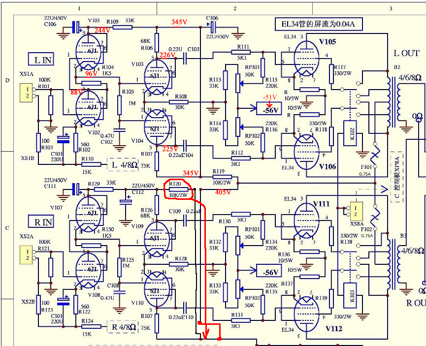
The only schematic of this amplifier known is the one obtained from Song at Canadian HiFi Online. The schematic in question represents the electronic configuration of a specific amplifier model. This schematic is crucial for understanding the circuit's operation, including...
DIY Homemade Tesla Coil Tuner. Instructions for constructing a Tesla Coil Tuner using readily available components. Determine the resonant frequency of Tesla Coil components. A Tesla Coil Tuner is an essential tool for optimizing the performance of a Tesla coil...
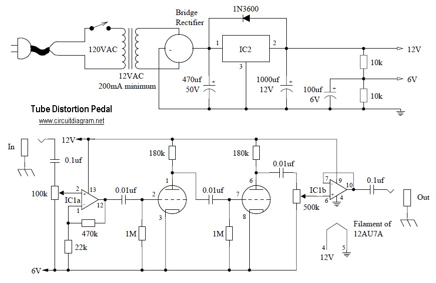
Tube distortion pedal circuit diagram. IC1: 747 dual op-amp; other ICs may be substituted, but the pinout will differ, so the datasheet should be checked. IC2: LM340K-12V voltage regulator. All resistors are 1/2 W. The bridge rectifier is a...