
DIY Homemade Tesla Coil Tuner
A Tesla Coil Tuner is an essential tool for optimizing the performance of a Tesla coil by tuning it to its resonant frequency. The resonant frequency is the frequency at which the coil operates most efficiently, allowing for maximum energy transfer and output. To create a DIY Tesla Coil Tuner, one can utilize components that are commonly found in electronic hobbyist kits or local electronics stores.
The construction process begins with the selection of a suitable inductor and capacitor combination. These components form a resonant LC circuit, which is crucial for tuning. The inductor can be a coil of wire wound around a non-conductive core, while the capacitor can be a variable capacitor that allows for fine-tuning of the circuit. A frequency counter or an oscilloscope may be employed to measure the frequency of the output signal accurately.
To assemble the tuner, the inductor is connected in series with the variable capacitor. Additional components, such as resistors and diodes, may be included to ensure stability and protect against voltage spikes. The output of the LC circuit can then be connected to the Tesla coil circuit, allowing for adjustments to be made while monitoring the resonant frequency.
Overall, the DIY Tesla Coil Tuner serves as an invaluable tool for enthusiasts and researchers alike, enabling them to explore the fascinating properties of Tesla coils and their applications in wireless energy transmission and high-voltage experiments. Proper attention to component specifications and safety precautions is essential during the construction and operation of the tuner to ensure effective and safe performance.DIY Homemade Tesla Coil Tuner. How to make a Tesla Coil Tuner from easily obtainable parts. Find the resonant frequency of Tesla Coil parts.. 🔗 External reference
Related Circuits
Due to the low coupling coefficient, the primary self-inductance tends to short out the driving signal. However, utilizing a series/parallel set of capacitors for energy coupling increases the input impedance at resonance, thereby achieving good power transfer efficiency. The...
As the position of the sun changes, the illumination level on the light-dependent resistors (LDRs) also varies, causing the input voltage for the window comparator to deviate from half of the supply voltage. Consequently, the output of the comparator...
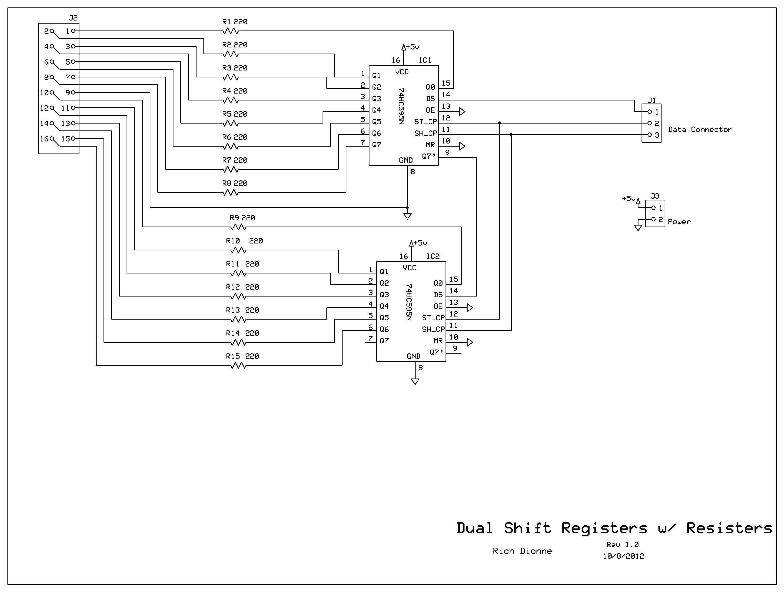
Control the two digits representing minutes; this circuit includes two shift registers, 30 resistors, and 30 LEDs. The schematic illustrates the design. As the circuit design neared completion, it became evident that soldering all components onto a basic prototyping...
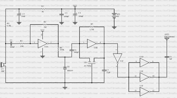
The RF oscillator using the inverter N2 and 10.7MHz ceramic filter is driving the parallel combination of N4 to N6 through N3. Since these inverters are in parallel, the output impedance will be low so that it can directly...
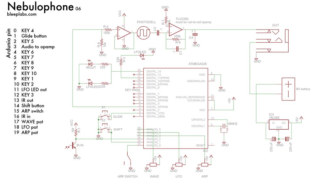
The initial intention was to purchase a Nebulophone; however, the price exceeded the budget. It was discovered that programming an AtMega 328 using ArduinoISP was a feasible alternative. If the code was compatible with Arduino, it was logical to...
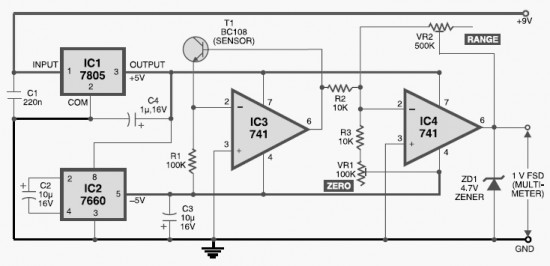
This DIY digital thermometer circuit can measure temperatures up to 150°C with an accuracy of ±1°C. The temperature is displayed on a 1V full scale deflection. The digital thermometer circuit is designed to provide accurate temperature readings within a specified...