
SMD project

The project focuses on designing a compact headphone amplifier using Surface Mount Device (SMD) technology. The use of SMD components allows for a reduction in the overall size of the circuit, which is particularly advantageous for portable audio applications.
The circuit typically includes a power supply section, an audio input stage, an amplification stage, and an output stage. The power supply can be derived from a single-cell lithium-ion battery, allowing for a compact and efficient design.
For the audio input, a 3.5mm jack can be used to connect external audio sources. The input signal may be coupled through capacitors to block any DC offset, ensuring that only the AC audio signal is amplified.
The amplification stage can utilize an operational amplifier (op-amp) configured for gain, or a dedicated headphone amplifier IC. The choice of components will depend on the desired output power and quality. SMD op-amps such as the LM358 or dedicated headphone amplifiers like the PAM8403 can be employed, depending on the application requirements.
Finally, the output stage drives the headphones directly. It is crucial to ensure that the output impedance is matched to the headphones for optimal performance. Additionally, decoupling capacitors should be placed close to the power supply pins of the amplifier to minimize noise and improve stability.
The layout of the PCB should be carefully designed to minimize signal interference and ensure proper grounding. Ground planes are recommended to reduce noise, and traces should be kept short and wide to handle the current efficiently.
In summary, this SMD headphone amplifier project combines compact design with effective audio performance, making it suitable for a variety of portable applications.This my fist project with SMD circuit. I ignored SMD because the small sized parts are confused me. The circuit of current SMD project is the headpho.. 🔗 External reference
Related Circuits
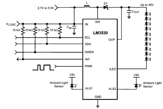
A simple white LED driver circuit can be designed using the LM3530 high-efficiency white LED driver IC, which features programmable ambient light sensing capability and an I2C compatible interface. The LM3530 LED driver can control up to 11 series...
This battery-powered monitor is designed to provide an audible indication of keying for transceivers that lack a CW sidetone. Its sensor wire is wrapped around the transceiver's coax, eliminating the need for a direct connection. While primarily intended for...
Building ESLs involves the use of tools and materials that if handled improperly can be hazardous. Please make sure you know how to use these things before you begin. By all means, use safety glasses at all times. If...

An adjustable laboratory power supply capable of providing an output voltage range from 0 to 60 volts can be constructed using the provided circuit diagram. This power supply can utilize the LM723 chip for lower voltage applications or, for...
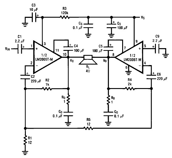
A simple 20-watt amplifier electronic project can be designed using the LM2005 dual high-power amplifier, which is engineered to provide optimal performance and reliability for automotive applications. The LM2005 20-watt amplifier has a high current capability of 3.5A, allowing...
This project operates red, amber, and green LEDs in the correct sequence for a single UK traffic light. The duration of the complete sequence—red, red & amber, green, amber—can be adjusted from approximately 7 seconds to about 2.5 minutes...