
Soft Light Dimmer Circuit

The circuit operates by utilizing a timer that is triggered on the zero crossing of the input voltage, ensuring synchronous operation with the AC waveform. The time constant, determined by capacitor C5 in conjunction with resistors R14 and R15, plays a critical role in defining the conduction angle of the IGBT (Insulated Gate Bipolar Transistor), which is crucial for controlling the output power delivered to the load.
Transistors T2 and T3 are configured to act as a safety mechanism, inhibiting the power switch until the auxiliary supply voltage stabilizes at 8V. This prevents premature activation of the IGBT, ensuring that it operates under optimal conditions. The gate of the IGBT is sensitive to voltage levels; therefore, maintaining the correct gate voltage is essential for reliable operation.
Resistor R5 is integral to the circuit's protection scheme. It is designed to sense the current flowing through the circuit. In the event of a short circuit or over-current condition, the voltage drop across R5 will rise, eventually reaching the gate trigger voltage of the sensitive gate thyristor. This triggers the thyristor to turn off the IGBT by pulling its gate low, thus interrupting the power flow and protecting the circuit from damage.
Additionally, the circuit's design incorporates a soft-start feature. When power is initially applied, the current limiting action provided by R5 prevents excessive inrush current, allowing the system to gradually ramp up to full operational levels. This not only protects components from damage but also enhances the overall reliability and longevity of the circuit. The timer's ability to reset simultaneously upon triggering the thyristor ensures that the system remains in a safe operating state, ready for subsequent cycles of operation. This comprehensive approach to circuit design emphasizes both functionality and safety in power management applications.The timer is triggered on the zero crossing voltage pulse. The time constant is determined by C5/R14+R15 that is used to determine the conduction angle. The T2 T3 inhibits the power switch until the auxiliary supply voltage reaches 8V to guarantee that the gate of the IGBT receives correct voltage level. R5 is the current sense resistor that i s used for the short circuit and over-current protection. The gate of the IGBT will taken low and turn off, when the voltage across R5 reaches the sensitive gate thyristor gate trigger voltage. At the same time the timer will reset. This current limiting also provides protection against excessive in-rush current and automatic soft-start.
[Source: STMicroelectronics Application Note] 🔗 External reference
Related Circuits
An advantage of a photogate over a sound trigger is that the former activates based on the exact position of the object that interrupts the beam. For instance, the shape of a snapped elastic cord can be captured as...
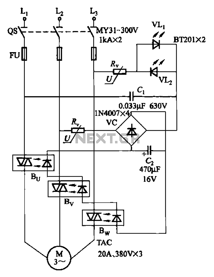
The circuit depicted in Figure 3-93 is integrated with an optical phase sequence protection relay. The circuit in question is designed to provide phase sequence protection using an optical relay mechanism. Optical phase sequence protection relays are crucial in applications...
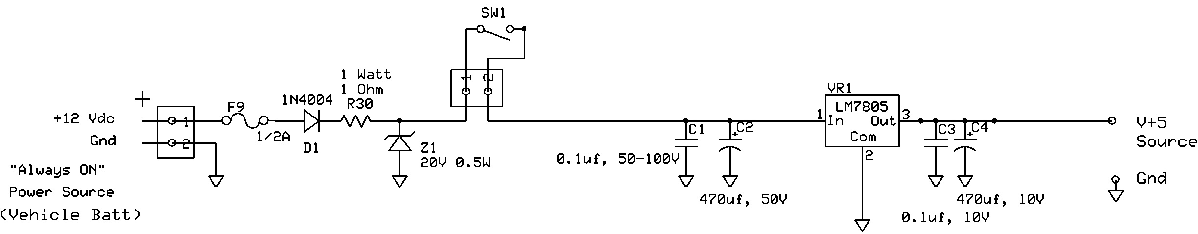
The circuit regulates approximately 12V from the car battery down to 5V for use by an Atmel AVR microcontroller. The presence of two capacitors on each side of the linear regulator LM7805 raises questions regarding their purpose. It is...
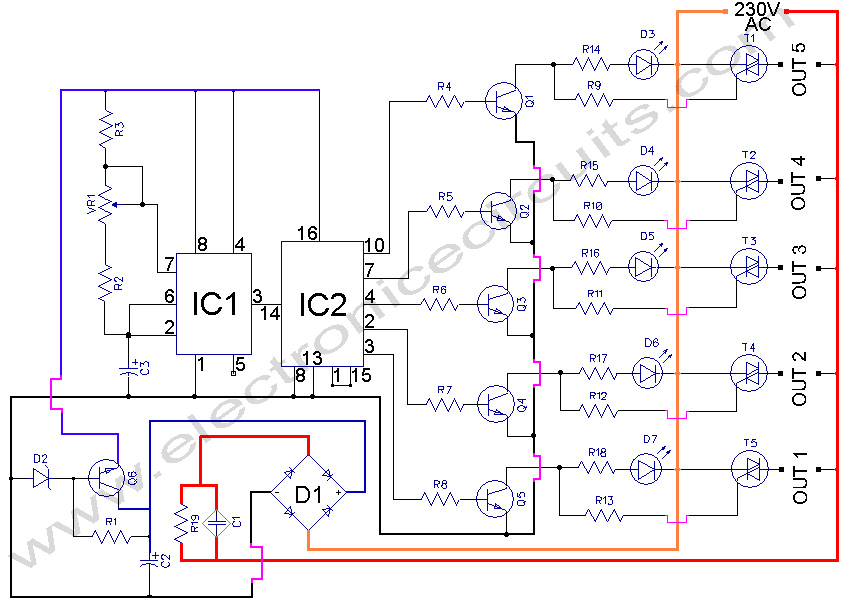
5 WAY AC FLASHER. These types of circuits are commonly used in various ceremonies such as the Wesak festival, Christmas, and weddings. This 5 WAY AC FLASHER circuit. The 5 Way AC Flasher circuit is designed to produce a sequential...
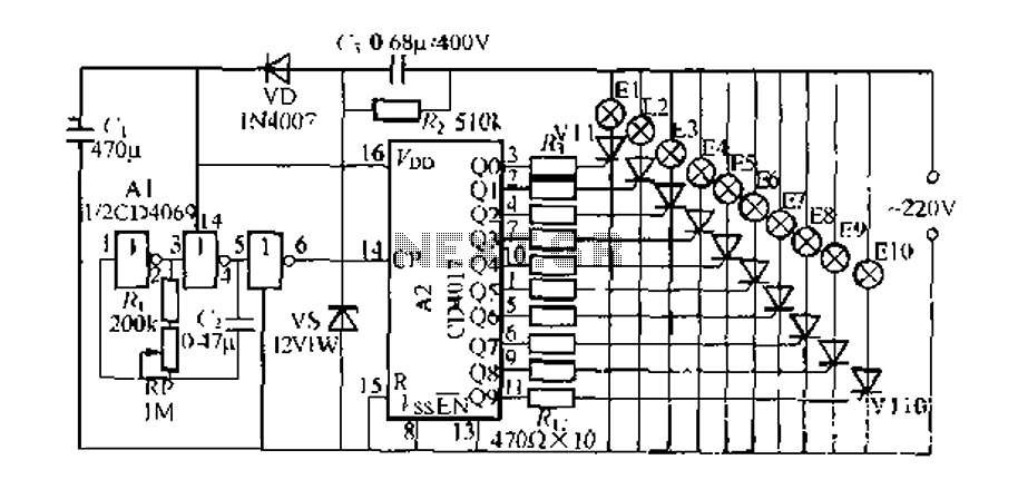
The digital integrated circuit consists of a controller for a string of ten road flashing lights, which drives the El-El0 string lights in a flashing cycle. The system utilizes a ten-count decoder, specifically the CD4017 digital integrated circuit. When...
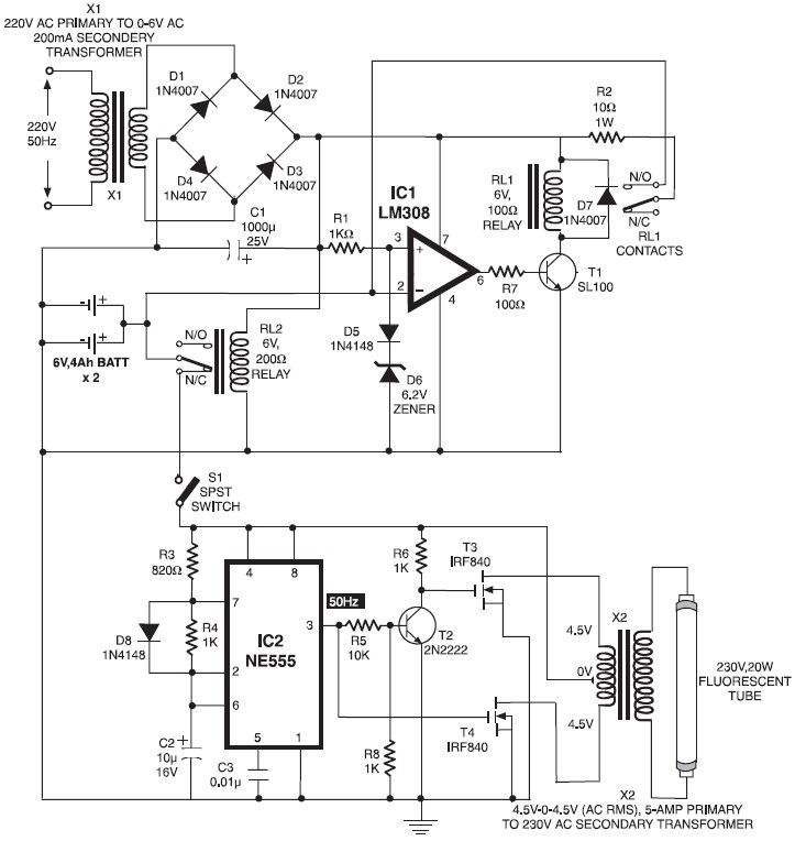
When mains power is absent, relay RL2 remains in a de-energized state, supplying battery power to the inverter section through its normally closed contacts and switch S1. The inverter section consists of IC2 (NE555), configured in astable mode to...