
Three-way operation allows the motor-controlled circuits
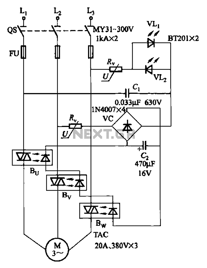
The circuit in question is designed to provide phase sequence protection using an optical relay mechanism. Optical phase sequence protection relays are crucial in applications where the correct phase sequence is necessary for the proper operation of three-phase motors and other equipment. The relay operates by monitoring the phase sequence and ensuring that it adheres to the required configuration.
In this circuit, the optical relay is likely to utilize phototransistors or photodiodes to detect the phase sequence. The input from the three-phase supply is fed into the relay, which analyzes the phase relationships between the three lines. If the sequence is correct, the relay remains in a closed state, allowing current to flow to the load. Conversely, if an incorrect phase sequence is detected, the relay opens, thereby disconnecting the load and preventing potential damage to the equipment.
The circuit may also include additional components such as resistors, capacitors, and diodes to filter signals and stabilize the operation. The design must ensure that the relay operates within specified voltage and current ratings to avoid false triggering or failure. Furthermore, the layout of the circuit should minimize electromagnetic interference (EMI) and ensure reliable operation in various environmental conditions.
Overall, this circuit serves as a critical protective measure in industrial and commercial applications, safeguarding motors and other three-phase devices from phase sequence-related failures. Circuit shown in Figure 3-93. It is coupled with optical phase sequence protection relay.
Related Circuits
This is a simple yet effective darkness activator. It uses a light-dependent resistor (LDR) to detect light, and when no light is present, it activates an alarm from an 8-ohm speaker. The circuit can be easily modified to function...
This page provides information on circuits that can trigger stroboscopes from external circuits. The circuits are designed to be integrated into stroboscope systems, allowing them to be activated using an external trigger pulse. The standard trigger pulse utilized in...
The circuit utilizes a 4-bit encoder to generate data, which is then modulated using an RF modulator for transmission. On the receiving end, the signal is demodulated, and a decoder retrieves the 4-bit data. The pin configuration for the...

The machine model, commonly used for ESD testing in Japan, is a more severe ESD test. This model simulates metallic contact between the device under test and a charged body. The source capacitor is 200pF with no limiting resistor....

The following circuit is a power amplifier circuit for an FM transmitter with an output power of 30 watts. The power amplifier circuit utilizes a power transistor of type 2SC1946A. The FM transmitter operates with a 13.8-volt DC power...

Cooling an instrument or device can enhance the signal-to-noise ratio (SNR) and extend the product's lifespan. For instance, the dark-and-noise signal of an infrared detector's output at room temperature can be significantly reduced when cooled. A custom cooling device...
Warning: include(partials/cookie-banner.php): Failed to open stream: Permission denied in /var/www/html/nextgr/view-circuit.php on line 713
Warning: include(): Failed opening 'partials/cookie-banner.php' for inclusion (include_path='.:/usr/share/php') in /var/www/html/nextgr/view-circuit.php on line 713