
Solar Charger Circuit for 6V 4.5Ah Battery
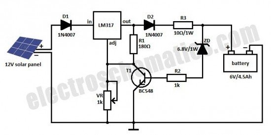
The solar charger circuit typically consists of several key components, including a solar panel, a charge controller, and the battery storage system. The solar panel converts sunlight into electrical energy, which is then directed to the charge controller. The charge controller regulates the voltage and current coming from the solar panel to ensure that the batteries are charged efficiently and safely, preventing overcharging and potential damage.
In this circuit, a diode is often included to prevent reverse current flow, which could discharge the batteries back into the solar panel during low-light conditions. Additionally, capacitors may be used to smooth out the voltage output from the solar panel, ensuring a stable charging process.
For Lead Acid batteries, the circuit may include a voltage regulator to maintain the appropriate charging voltage, typically around 13.8 to 14.4 volts. For Ni-Cd batteries, the charging voltage is usually lower, around 1.4 to 1.5 volts per cell. The circuit can be designed with adjustable settings to accommodate different battery types and sizes.
Safety features might include thermal protection to prevent overheating and fuses to protect against short circuits. The overall design aims to provide an efficient and reliable method for harnessing solar energy to charge batteries, making it suitable for off-grid applications and renewable energy projects.Here is a solar charger circuit that is used to charge Lead Acid or Ni-Cd batteries using the solar energy power. The circuit harvests solar energy to char.. 🔗 External reference
Related Circuits
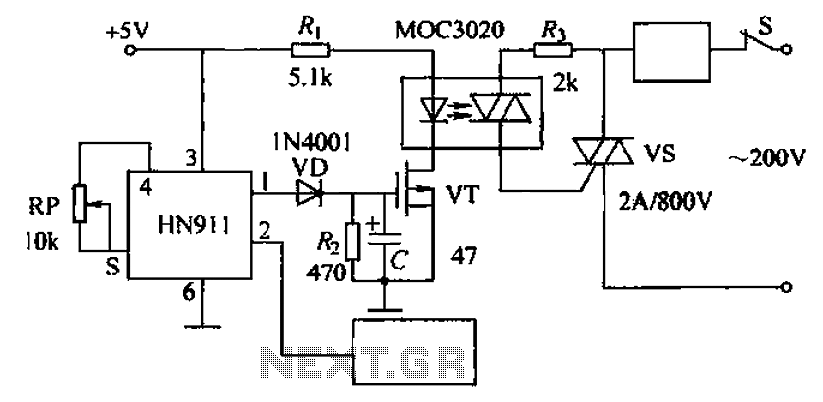
Automatic door control circuit diagram. It utilizes a pyroelectric infrared detection module, HN911, for human motion detection. A variable resistor (potentiometer) is used to adjust the delay time controlled by a transistor (VT). An optocoupler (MX: 3020) provides AC...
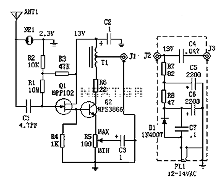
An active antenna operating within the frequency range of 100 kHz to 30 MHz, characterized by its compact size and effective performance. It is designed to be simple and low-cost, making it ideal for remote medium wave and short-wave...
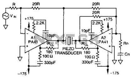
Using a PA41 from Apex Microtechnology, this monolithic amplifier is capable of 350-V operation and delivers 660 V peak-to-peak in a bridge circuit. The PA41 is a high-performance monolithic amplifier designed for applications requiring high voltage and high power output....
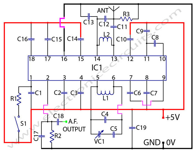
TDA7000 FM Radio Receiver Circuit Using Tuning Capacitor GENERAL DESCRIPTION The TDA7000 is a monolithic integrated circuit for mono FM. The TDA7000 is designed as a complete FM radio receiver circuit, integrating all necessary functions for receiving mono FM signals....
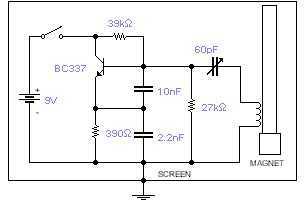
This basic oscillator will detect the Earth magnetic field. The ferrite rod and coil are taken from an old Medium Wave receiver and a small magnet is glued at one end. Tune to a medium wave commercial station until...
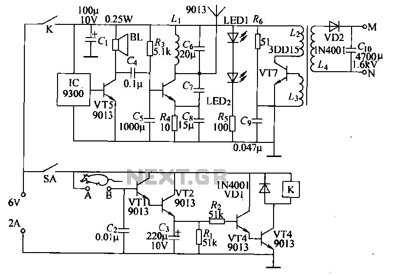
Power-saving electronic mousetrap. This example describes the minimal power consumption, which only occurs when a mouse enters the control zone during foraging activities. After a 30-second delay, the system enters a wait state, making it suitable for outdoor use....
Warning: include(partials/cookie-banner.php): Failed to open stream: Permission denied in /var/www/html/nextgr/view-circuit.php on line 713
Warning: include(): Failed opening 'partials/cookie-banner.php' for inclusion (include_path='.:/usr/share/php') in /var/www/html/nextgr/view-circuit.php on line 713