
Solar Panel AC Mains Relay Changeover Circuit
The automatic changeover relay circuit described operates by seamlessly switching between two power sources to ensure consistent battery charging. The circuit is primarily composed of an operational amplifier (IC 741), which is used to monitor the voltage levels from the solar panel. The operational amplifier serves as a comparator, determining when the solar panel output is insufficient for charging the battery.
The central component of the circuit is the LM317 voltage regulator, which is configured to maintain a constant output voltage of 7 volts. This output is critical for charging the 6V battery efficiently. The LM317 is connected in such a way that it can provide a steady current, crucial for the longevity and performance of the battery.
When the solar panel output falls below the threshold of 7 volts, the relay is activated, disconnecting the solar panel and connecting the AC/DC adapter to the LM317. This transition is essential for maintaining battery charge during periods of low solar energy, such as at night or during cloudy weather. The AC/DC adapter ensures that the battery continues to receive power, preventing discharge and maintaining its charge state.
The relay used in the circuit is typically a double-pole double-throw (DPDT) type, which allows for the switching of both the solar panel and the AC adapter connections. This design ensures that only one power source is connected to the battery at any given time, preventing potential damage from simultaneous connections.
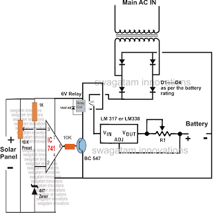
Overall, the automatic changeover relay circuit effectively combines renewable energy input with traditional power sources, providing a reliable solution for battery charging in various conditions. The integration of these components ensures that the system is efficient, responsive, and capable of maintaining battery health over extended periods.The discussed automatic change over relay circuit was requested by Mr. Karimulla Baig. The circuit normally charges the connected battery at constant current through the power received from the solar panel, andrevertsto DC power from an AC/DC adapter in the absence of solar energy (during night time). Lets the read the request in more details: i ha ve made the both chargers of both AC mains charger and solar Charger and i need a change over for this kindly help me in designing the change over circuit. Looking at the proposed circuit diagram, we see three basic stages, on the left an IC 741 circuit, at the center a voltage regulator stage using IC LM317, while on the top an AC/DC adapter circuit.
The IC317 circuit is a regulator circuit, configured for generating aconstantcurrent, 7 volts output to the 6V battery which is connected at the given points. However, the moment the panel voltage drops below 7 volts, the relay switches OFF, connecting the DC adapter power with the regulator circuit, and now the batterystartsgetting charged through the AC/DC adapter voltage source.
🔗 External reference
Related Circuits
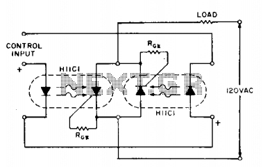
If load current requirements are relatively low (i.e., maximum forward RMS current of 500 mA), an AC solid-state relay can be constructed quite simply by connecting two H11C optically coupled SCRs in a back-to-back configuration as illustrated. The proposed circuit...
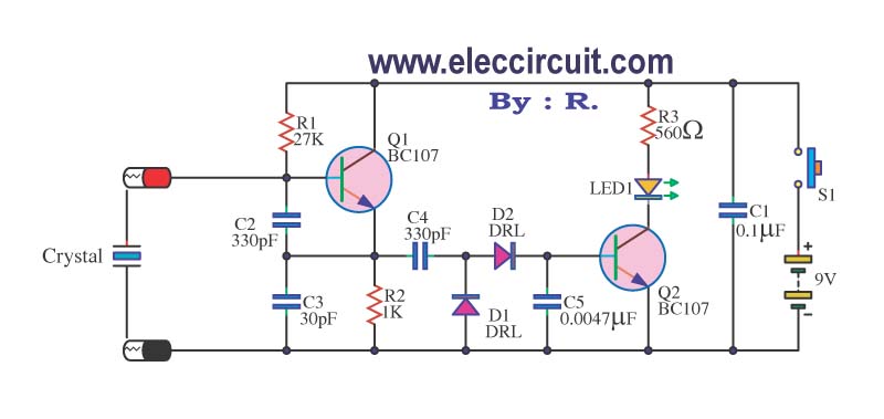
A multimeter cannot be used to test a crystal oscillator. Instead, a dedicated circuit is required, capable of checking crystals within the frequency range of 100 kHz to 900 MHz. This circuit is easy to construct and cost-effective. To construct...
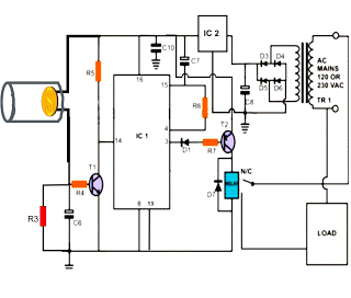
The following post illustrates a simple light-operated remote control circuit that can be activated by an ordinary flashlight or, more effectively, through a laser beam unit (keychain type). The Light Dependent Resistor (LDR) is connected between the base of...
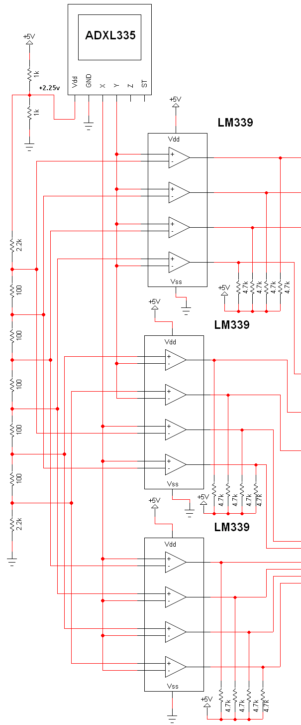
The schematic for this project is extensive, and the complete schematic is displayed below. It is divided into two sections: the analog and digital sections. The schematic illustrates the analog-to-digital conversion circuit, which includes 12 comparators—6 for the X-axis...
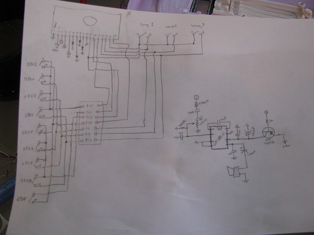
A recent thrift shopping experience revealed a toy that appears to be suitable for circuit bending. The toy was found without batteries, preventing any testing at the store. It may be beneficial to bring batteries during future visits or...
Construct a low-cost and relatively simple robot that activates whenever a desk lamp is illuminated. The design does not incorporate any sensors. This robot can be designed using basic electronic components to create a simple activation mechanism based on light...